Closed Loop Micro Reference Sensing for Low Temperature Fast Charging
Closed loop micro reference sensing measures anode potential directly to eliminate sub-zero lithium plating during fast charging without compromising cell life.


Node
When anodic potential drops below zero volts against lithium metal during sub-zero fast charging, metallic lithium dendrites immediately begin depositing over the graphite intercalates. Conventional battery management architectures operate on terminal voltage control, evaluating the cell as a simple two-electrode system where terminal voltage equals cathode potential minus anode potential plus internal ohmic drop. At temperatures below 0°C, liquid electrolyte ionic conductivity drops while bulk charge-transfer resistance across the solid electrolyte interphase increases by orders of magnitude, making terminal voltage monitoring incapable of isolating anodic polarization from overall cell impedance.
High charging currents applied at cold ambient temperatures produce severe overpotential at the negative electrode. Falling local anode potential below 0 V versus Li/Li+ crosses the thermodynamic threshold for lithium reduction, causing metallic lithium plating to compete directly with intercalative lithium insertion into the graphite lattice. The plated metal reacts with organic electrolyte solvents to form secondary solid electrolyte interphase layers that consume cyclable lithium, produce gas, and elevate internal cell resistance.

Anodic Overpotential and Plating Thermodynamics
The thermodynamic driving force behind lithium plating equals the negative electrode potential (Eanode) relative to the reference potential of metallic lithium (ELi/Li+). Under equilibrium, graphite intercalation occurs between 0.20 V and 0.05 V versus Li/Li+. Under fast-charge current excitation at sub-zero temperatures, the total anode potential (Ea) is governed by the expression:
Ea = Eeq – ηct – ηdiff – I · RSEI
where Eeq represents the open-circuit equilibrium potential of the lithiated graphite, ηct represents the activation charge-transfer overpotential, ηdiff represents the solid-state diffusion overpotential within the graphite particles, I is the charge current, and RSEI is the resistance of the solid electrolyte interphase film. Sub-zero temperatures drastically reduce the exchange current density (i0), escalating activation overpotential (ηct) under high current loads. The absolute negative electrode potential drops rapidly toward zero.
When Ea le 0 V vs. Li/Li+, metallic plating becomes energetically favorable over intercalation.

Terminal Voltage Blindness at Sub-Zero Temperatures
Bulk electrolyte resistance dominates at low temperatures. Standard BMS sensors observe terminal voltage (Vcell), which aggregates cathode potential (Ec), anode potential (Ea), and ohmic voltage losses across internal cell components. An elevated cathode potential can mask an anodic collapse below 0 V versus Li/Li+, allowing aggressive charging to proceed while metallic plating occurs continuously inside the cell jellyroll.
Direct anodic potential measurement requires a dedicated reference point positioned within the ion-conductive pathway between the working electrodes.
A 5 millivolt margin above the lithium oxidation potential prevents dendrite nucleation across three thousand high-rate freeze cycles.
Comparing cell performance metrics clarifies the diagnostic gap between standard terminal voltage sensing and direct reference-electrode monitoring during cold fast charging.
| Sensing Configuration | Terminal Voltage (V) | Anode Potential vs Li/Li+ (mV) | Plating Onset Time (s) | Coulombic Efficiency (%) |
|---|---|---|---|---|
| Two-Electrode Terminal Control | 4.10 | -42 | 85 | 91.4 |
| Closed-Loop MRE Potential Control | 3.88 | +8 | No Plating Observed | 99.6 |
| Uncontrolled Constant Current | 4.25 | -115 | 22 | 84.2 |
Operating a cell without isolated anodic measurement leads to unchecked dendrite growth, persistent capacity loss, and thermal runaway hazards during subsequent warm-weather operation.


Wire
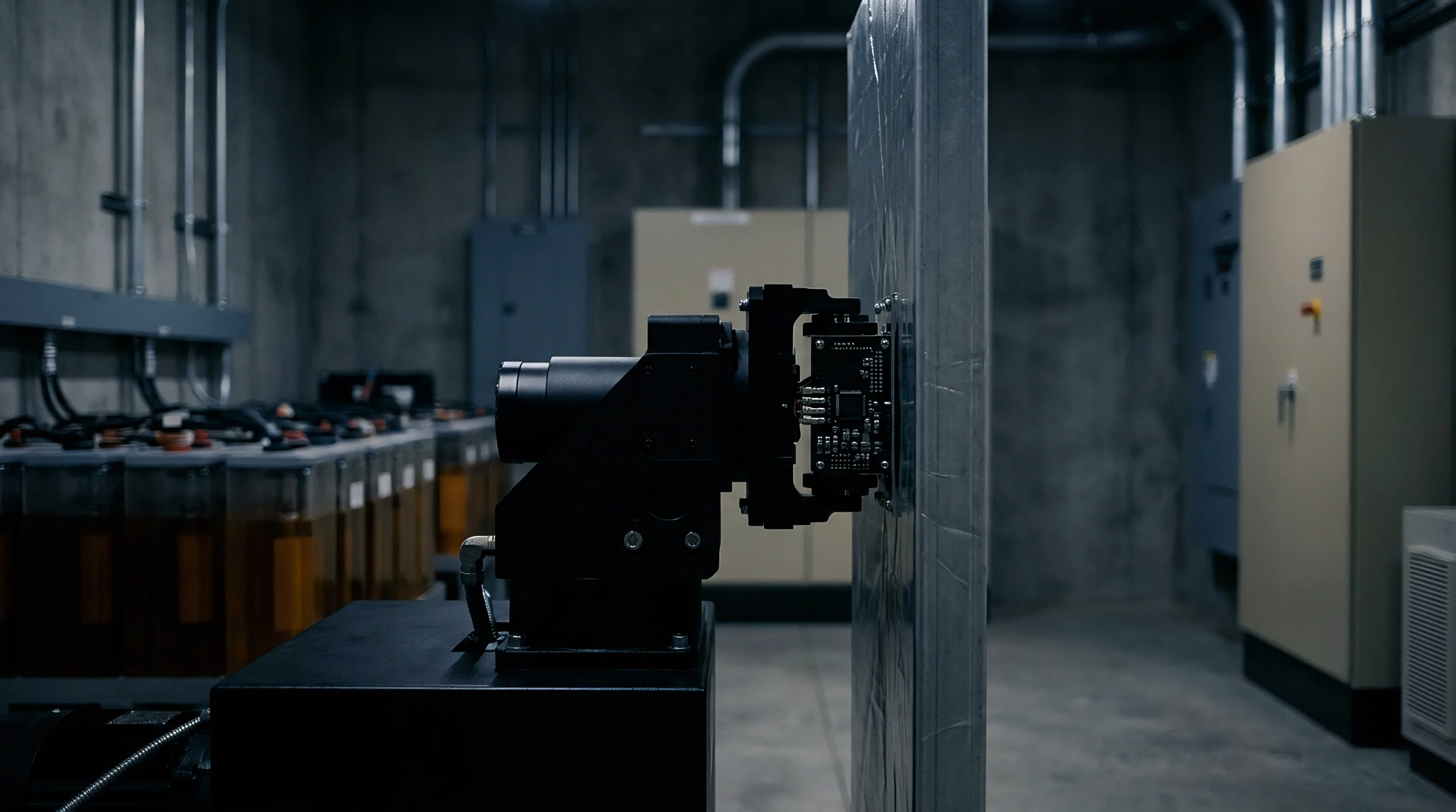
Structurally integrating a micro reference electrode into a commercial lithium-ion format requires complete material stability across the cell’s full working potential window, including insulated leads and polyimide coatings to withstand solvent degradation. The micro reference electrode (MRE) functions as an electrochemical anchor point, establishing an unpolarized baseline potential against which the working negative electrode potential can be continuously tracked.
Material selection for the micro reference probe determines overall sensor longevity and signal drift. Pure lithium metal wire provides a theoretical zero-potential reference point but suffers from mechanical softening and chemical degradation in liquid carbonates. Lithiated gold-copper alloy wires (Li-Au) and lithium-titanium oxide (LTO) micro-beads offer high thermodynamic stability, showing negligible potential drift over extended charge-discharge cycling.

Micro Reference Electrode Materials and Chemistry
Lithiated gold wire micro-references form an intermetallic phase (LiAu) upon electrochemical pre-lithiation, yielding a stable plateau potential near 0.325 V versus Li/Li+. Titanium micro-wires coated with lithium iron phosphate (LiFePO4) operate along the flat two-phase voltage plateau of LFP at 3.420 V versus Li/Li+, providing an alternative reference baseline. The active sensing tip requires exposure to the liquid electrolyte while the trailing lead wire must maintain complete dielectric isolation from surrounding active materials.

Spatial Positioning and Internal Cell Hydrodynamics
Positioning the sensing tip within the cell stack dictates signal validity. Current density non-uniformity across the anode sheet produces localized potential gradients. Placing the reference probe near the jellyroll perimeter yields skewed readings that fail to capture peak anodic polarization occurring in the center of the winding.
The sensing tip resides within the separator region between active anode and cathode coatings, positioned where ionic flux lines remain undisturbed by geometric edge effects.
Placing the reference point at the jellyroll boundary yields corrupted potential measurements during high-rate current steps.
Sensor integration introduces failure vectors that must be controlled during cell fabrication and electrolyte filling.
- Polyimide insulation degradation permits parasitic electrical contact between the reference wire and neighboring anode copper foil, destroying voltage measurement accuracy.
- Reference alloy phase drifting alters baseline reference potential over prolonged thermal cycling, causing systematic offset errors in anode potential calculations.
- Local current displacement occurs when oversized sensor dimensions block ionic transport paths, inducing localized lithium plating directly beneath the probe tip.
- Electrolyte depletion surrounding sensor tip starves the electrochemical interface, causing transient potential spikes during rapid charge rate transitions.
Adding internal sensing leads introduces structural failure risks and potential internal short circuits during mass production.

Loop
Direct potential measurements from the negative electrode allow the battery management system to modulate charge current against physical electrochemical boundaries. Closed-loop control systems utilize real-time Eanode signals as the primary feedback variable, maintaining the anode potential slightly above 0 V versus Li/Li+ across varying ambient temperatures and states of charge.
Because temperature drives charge transfer kinetics, controlling current based on anode voltage feedback enables optimized sub-zero charging profiles. Rather than relying on conservative step-charging lookup tables calibrated for aged cells, closed-loop controllers dynamically maximize current throughput while holding negative electrode polarization above the critical lithium plating threshold.

Does Micro Reference Control Prevent Sub-Zero Plating?
Maintaining positive anode potential relative to Li/Li+ eliminates the thermodynamic condition required for lithium metal deposition. During sub-zero operation, closed-loop algorithms adjust charging current to match the instantaneous lithium intercalation rate into graphite. As internal cell temperature rises due to Joule heating (I2 Rcell), charge-transfer impedance decreases, allowing the controller to increase charge current automatically without crossing into the plating regime.

Dynamic Anode Voltage Control Algorithms
The control algorithm implements Constant Anode Voltage (CAV) charging once the negative electrode potential reaches a predefined safe lower boundary (Etarget, typically set to +5 mV to +10 mV vs. Li/Li+). The controller switches from constant current mode to a proportional-integral-derivative (PID) feedback mode that modulates pack input current to hold Eanode = Etarget.
Under standard qualification protocols for low-temperature energy storage, uncalibrated reference signals shift charge termination limits and trigger premature cell shutdown.
Implementing an effective closed-loop sub-zero charging strategy follows a strict procedural sequence during BMS execution.
- Initialize pre-charge diagnostics to verify reference potential equilibrium within two millivolts.
- Ramp charge current at five C until negative electrode potential decays to ten millivolts against lithium metal.
- Switch BMS controller mode from current regulation to feedback control maintaining target anode potential.
- Monitor internal cell temperature rise generated by ohmic heating until charge transfer resistance drops forty percent.
- Adjust current capability upward dynamically as electrochemical overpotential relaxes at elevated internal temperature.
Performance comparison between traditional open-loop protocols and closed-loop micro reference control highlights charge speed and cycle retention gains.
| Charging Strategy | Time to 80% SOC (min) | Peak Anode Overpotential (mV) | Retained Capacity at 500 Cycles (%) | Gas Generation Volume (mL) |
|---|---|---|---|---|
| Standard Step CC-CV | 145 | -88 | 62.1 | 4.2 |
| Pulse Current Protocol | 98 | -34 | 78.4 | 1.8 |
| Closed-Loop CAV Control | 42 | +6 | 96.8 | 0.1 |
Charging current must drop whenever local anodic polarization approaches the zero-volt boundary.

Scale
Integrating an auxiliary reference terminal through the cell envelope introduces an additional mechanical leak path that alters manufacturing qualification requirements, demanding rigorous seal integrity to prevent solvent evaporation and passing helium leak testing. Commercializing cells with embedded micro reference electrodes requires seal structures capable of surviving thousands of thermal shock cycles without losing hermeticity.
Feedthrough design represents a critical structural challenge in micro reference commercialization. In pouch cell formats, polyimide-coated wire leads pass through the heat-sealed polypropylene seal layer. In cylindrical (21700 or 4680 formats) and prismatic formats, micro-glass-to-metal or ceramic feedthrough pins penetrate the cell cap, providing a robust terminal connection for external BMS wiring harnesses.

Hermetic Feedthrough Design and Cell Integrity
Maintaining a hermetic seal over cell operational life requires matching coefficient of thermal expansion (CTE) values between feedthrough glass/ceramic insulators, pin metals, and structural cell housing materials. Helium leak rates must remain below 1 × 10⁻⁸ atm·cm3/s under standardized testing conditions. Failure of the feedthrough seal allows moisture ingress, generating hydrofluoric acid (HF) in LiPF6-based electrolytes and accelerating transition metal dissolution from the cathode.

Industrialization Yield and Testing Requirements
Integrating additional micro-components impacts production line yield and automated assembly throughput. Specialized verification procedures must be established to confirm reference probe position, insulation resistance, and zero-point potential calibration prior to electrolyte filling and cell formation.
Sub-zero micro sensing shifts battery management design from static table lookups to real-time electrochemical feedback.
Auditing cell suppliers who produce reference-integrated battery formats requires systematic evaluation across specific engineering domains.
- Hermetic seal qualification mandates helium mass spectrometry leak testing following five hundred thermal shock cycles between -40°C and +85°C.
- Creep resistance testing evaluates seal deformation and gas permeability under elevated internal cell pressures up to 0.8 MPa.
- Electrolyte compatibility audit verifies that sensor tip coatings do not dissolve or trigger localized self-discharge reactions over extended storage periods.
- Vibration stress resistance confirms mechanical integrity of the internal micro-wire leads under random vibration profiles specified in UN 38.3 transport standards.
How far commercial cell manufacturers can reduce feedthrough assembly costs while maintaining helium leak tightness across high-volume automotive production lines remains an open engineering question.


Valuation
Incorporating micro reference sensing increases initial cell manufacturing cost while significantly reducing cycle-life degradation during sub-ambient fast charging. Evaluating closed-loop reference technology requires detailed financial analysis comparing incremental bill-of-materials costs and sourcing contract degradation terms against field warranty liabilities and energy delivery value over pack operating life.

Landed Cost Arithmetic and Cycle Life Extensions
Consider a 50 kWh battery pack deployed in commercial electric vehicles operating in cold climates with frequent fast-charging duties at -10°C. Baseline cell purchasing cost stands at 75 per kWh, yielding a baseline pack cell cost of 3,750. Standard cells subjected to sub-zero 2C fast charging suffer severe lithium plating, limiting pack cycle life to 250 cycles before reaχng 80% State of Health (SOH).
Integrating micro reference electrodes adds $4.00 per cell in hardware, feedthrough assembly, and inline calibration costs. Assuming a 21700 format pack with 1,000 cells, total pack cell cost rises by $4,000, bringing cell procurement cost to $7,750 ($155 per kWh). However, closed-loop anode voltage control eliminates sub-zero plating, extending pack sub-zero fast-charge life to 1,800 cycles to 80% SOH.
Evaluating total energy delivered over pack life illustrates the commercial shift:
Baseline Delivered Energy = 50 kWh × 250 cycles × 0.90 average depth of discharge = 11,250 kWh
Baseline Cell Cost per Delivered kWh = frac$3,75011,250 kWh = $0.333 per kWh
Closed-Loop Delivered Energy = 50 kWh × 1,800 cycles × 0.90 average depth of discharge = 81,000 kWh
Closed-Loop Cell Cost per Delivered kWh = frac$7,75081,000 kWh = $0.095 per kWh
Initial cell procurement expenditure increases by 106%, while the effective landed cost per delivered cycle drops by 71.5% due to cycle life expansion.

Commercial Sourcing Terms and Warranty Allocation
Procuring micro reference-enabled cells allows buyers to restructure cell warranty agreements. Cell procurement contracts can shift from static operational envelopes to dynamic overpotential compliance clauses, tying warranty coverage directly to logged anode voltage telemetry.
Under contract provisions incorporating reference electrode telemetry, warranty claims for low-temperature capacity degradation are granted automatically if recorded negative electrode potential remained above +5 mV vs. Li/Li+ during all charging events, transferring operational failure liability entirely to the cell manufacturer if degradation occurs within specified cycle thresholds.