Anode Expansion Forces in Ultra-Thin Pouch Cells
Constraining ultra-thin pouch cells within a 0.05 to 0.30 MPa compliance window prevents separator crushing while arresting irreversible delamination.

Dilation
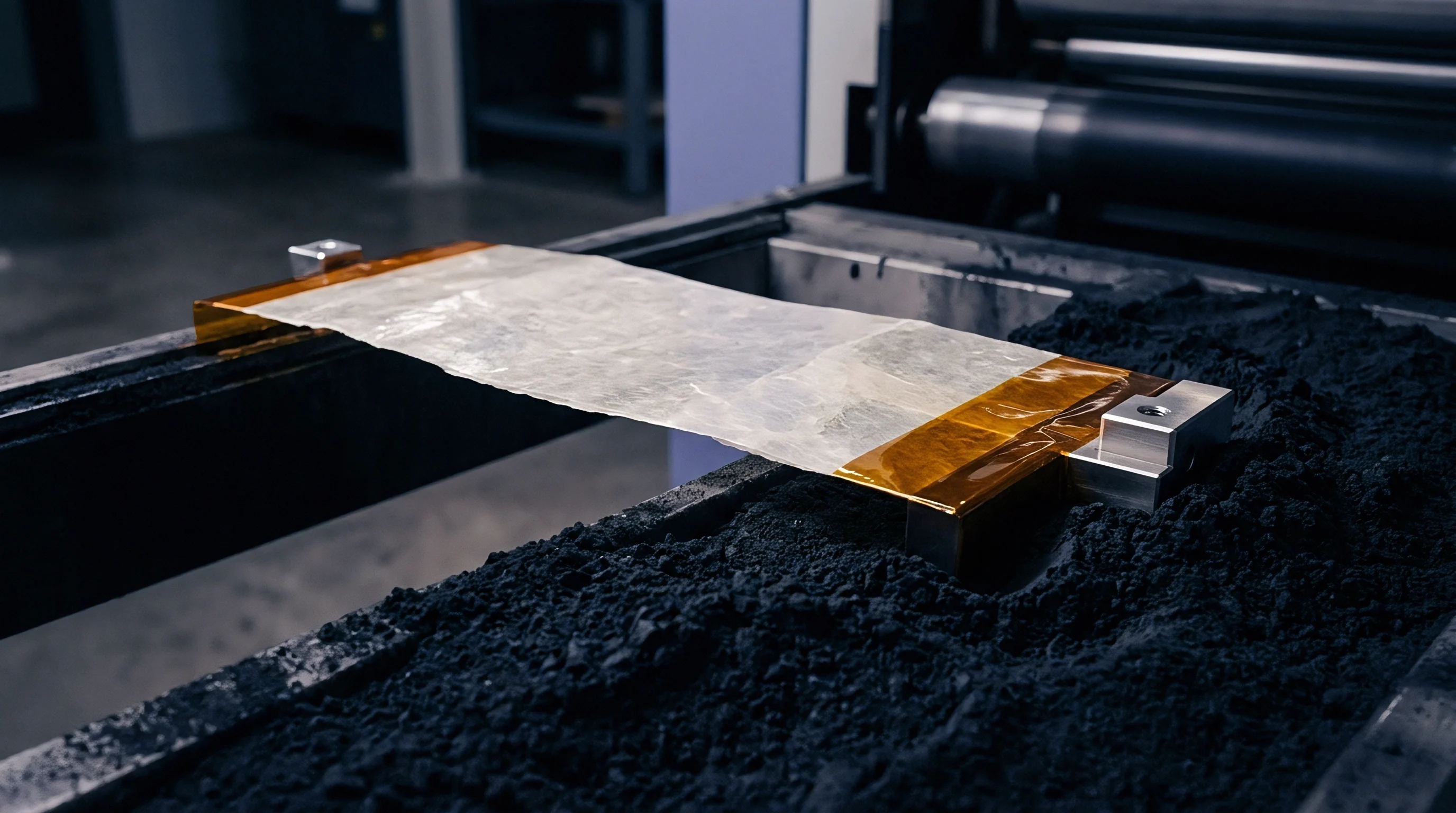
Intercalation of lithium ions into a graphite host lattice forces a crystallographic unit cell volume expansion of approximately ten percent along the c-axis during full lithiation. When cell designs incorporate silicon oxide or pure silicon nanoparticles to elevate volumetric energy density beyond 750 watt-hours per liter, this local expansion climbs past one hundred percent for the silicon phase. In ultra-thin pouch formats below three millimeters nominal thickness, anode breathing manifests as a severe mechanical boundary condition rather than a negligible packaging tolerance.
The active electrode stack transfers these microscopic lattice shifts directly into the exterior aluminum-laminated film without the rigid structural dampening found in heavy prismatic cans or cylindrical steel shells.
Electrode breathing divides into reversible operational swelling and irreversible aging drift. Reversible dilation tracks state of charge directly, peaking at full charge and contracting during discharge as lithium returns to the cathode. Irreversible expansion accumulates over field life through solid electrolyte interphase reconstruction, cathode transition metal dissolution, electrolyte dry-out, and continuous dead lithium deposition.
In a cell with a nominal initial stack thickness of 2.40 millimeters, reversible swelling adds 0.12 to 0.18 millimeters during each charge cycle, while calendar and cycling degradation add an unrecoverable 0.25 to 0.40 millimeters by eight hundred equivalent full cycles.
A cell operating at seventy percent state of health generates double the mechanical expansion force of a fresh cell under identical fixture displacement.
Thin pouch cells lack internal void space to absorb this displacement. The internal separator layers, typically nine to twelve microns of ceramic-coated polyethylene, compress under the expansion forces until their porous microstructure begins to close. Closing the separator pores throttles ionic conductivity, raises localized current density, accelerates overpotential growth, and initiates localized lithium metal plating at the electrode margins.
Unmanaged swelling creates a self-reinforcing failure loop: electrode expansion creates internal mechanical stress, stress damages the passivating interphase layer, fresh electrolyte consumes cyclable lithium to heal the layer, and the resulting reaction products drive further unrecoverable expansion.
| Active Anode Composition | Reversible Swelling Band | Irreversible Swelling at 800 Cycles | Unconstrained Free Displacement | Peak Constraint Stress at 100% SOC |
|---|---|---|---|---|
| Pure Artificial Graphite | 4% to 6% | 6% to 9% | 0.25 mm to 0.38 mm | 0.35 MPa to 0.55 MPa |
| Graphite with 5 wt% SiOx | 7% to 10% | 12% to 16% | 0.48 mm to 0.65 mm | 0.75 MPa to 1.10 MPa |
| Graphite with 10 wt% SiOx | 11% to 15% | 18% to 25% | 0.72 mm to 1.00 mm | 1.40 MPa to 2.10 MPa |
| Silicon-Dominant Composite | 22% to 35% | 35% to 55% | 1.40 mm to 2.25 mm | 3.50 MPa to 5.80 MPa |
Cell packagers frequently attribute early capacity drop-off to bad cathode batches when the true mechanism is unmanaged anode dilation choking the electrolyte pathways.


Plate
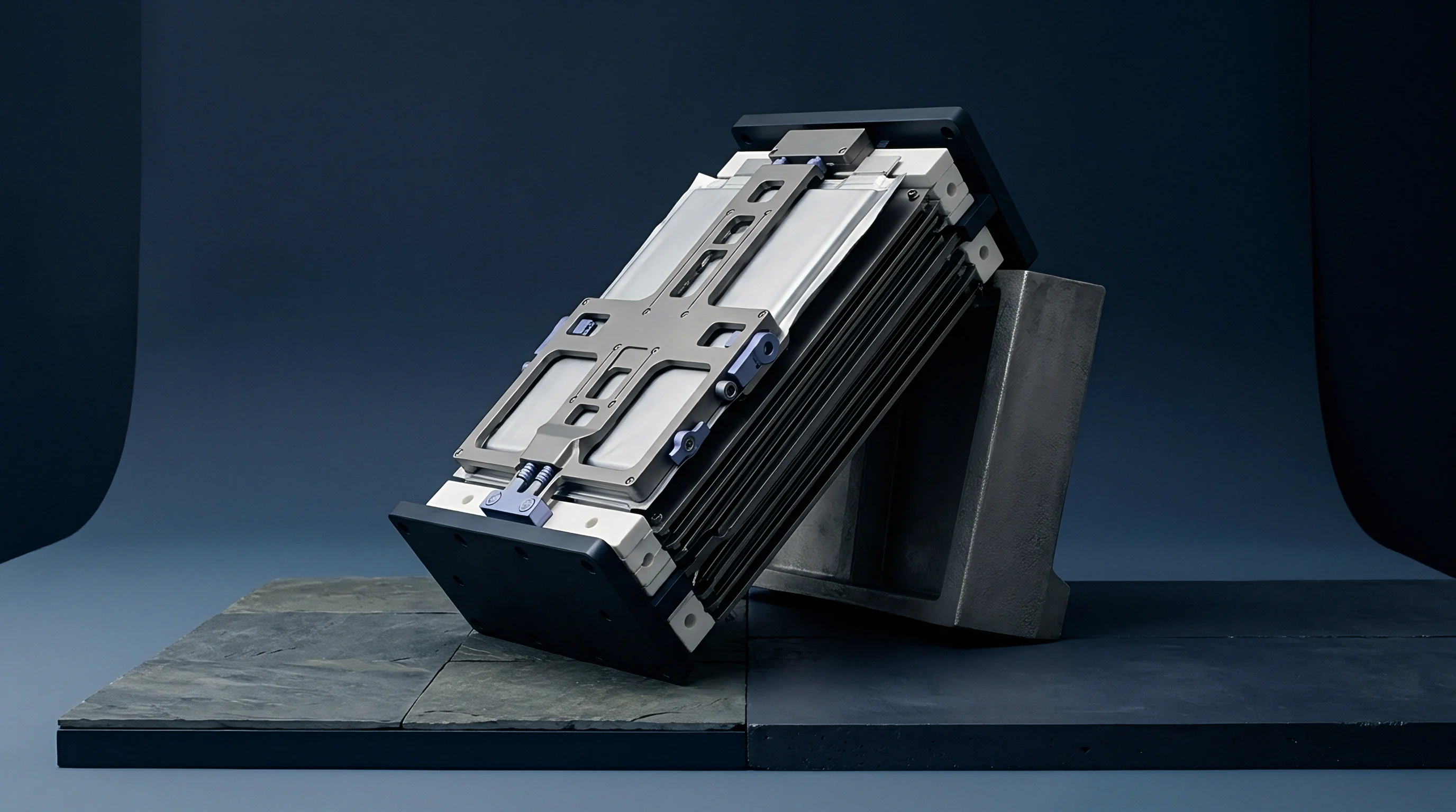
Restraining an expanding pouch cell requires sustained mechanical counter-pressure across the active face area. Zero-pressure boundaries allow anode particles to lose electrical contact with current collector foils during discharge contraction, isolating active material and degrading capacity retention within two hundred cycles. Excessive constraint pressure crushes the separator, pinches electrode edges, and induces localized copper foil tearing along the fold radii of stacked pouches.
The optimal operational window demands a continuous uniform stack pressure between 0.05 megapascals and 0.30 megapascals maintained through the entire cycle life of the device.

What Compliant Interlayer Prevents Cell Crushing?
Fixed rigid chassis cavities cannot maintain uniform pressure across the operational life of an expanding pouch. When aluminum plates lock a cell into a fixed volume, the combination of state of charge expansion and aging drift drives internal pressure past two megapascals, crushing internal layers. Designers place microcellular open-cell or closed-cell polyurethane elastomer pads between the cell face and the outer structural wall to absorb stack growth while exerting a predictable resistive force.
- Initial compression setting establishes the baseline contact force across the dry stack before the first charge, seating all internal foil layers flat against the separators.
- Elastic plateau loading accommodates the daily reversible breathing without swinging the surface pressure outside the specified electrochemical stability envelope.
- Densification phase control prevents the foam from bottoming out into a solid polymer block before the cell reaches its contractual end-of-life cycle target.
- Thermal relaxation margin preserves mechanical elasticity across the operating temperature span of negative twenty to sixty degrees Celsius.
The chosen elastomeric pad must operate strictly within its plateau stress region. High-density microcellular urethanes exhibit a flat stress-strain response between twenty percent and fifty percent deflection. Beyond fifty-five percent compression strain, the open cells collapse completely, entering densification where the elastic modulus escalates by orders of magnitude.
Entering the densification region destroys the compliance of the pack enclosure.
A compliant pad that bottoms out into solid urethane acts as a rigid anvil against the active foil margins.
An engineer selecting foam interlayers balances initial installation thickness, compressive force deflection rating, and compression set resistance. If the elastomeric pad suffers permanent deformation under sustained high-temperature storage, the assembly loses minimum clamp pressure during low-state-of-charge periods, driving premature impedance rise. Soft springs preserve cell health, hard boundaries shorten cell life.
Caliber
Instrumented testing of ultra-thin pouch expansion requires strict separation between test-fixture rigidity and actual enclosure compliance. Standard datasheets publish nominal cell thickness measured under a loose contact pressure of five to ten kilopascals using flat platens. That number reflects only shipping geometry.
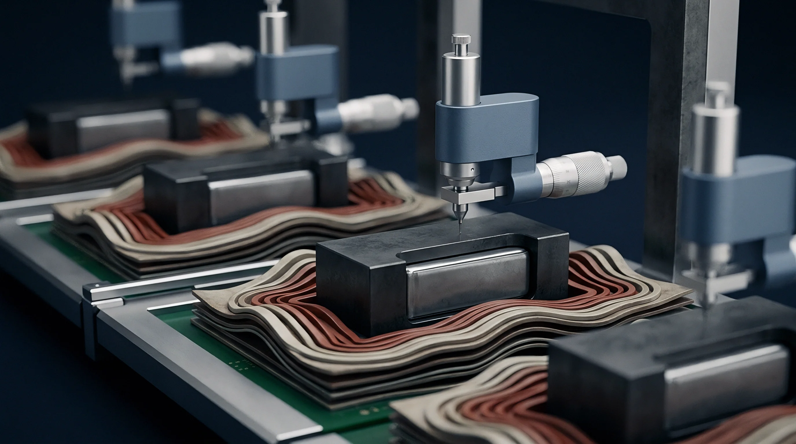
Measuring actual dynamic expansion forces requires high-precision screw-driven universal testing machines or custom pneumatic fixtures fitted with calibrated S-beam load cells, digital linear variable differential transformers, and temperature-controlled thermal chambers.

Dynamic Load Profiles across Cycling
Cycling a constrained pouch cell yields a characteristic force-displacement hysteresis curve. As charging progresses, force scales non-linearly with state of charge, displaying inflection points that align with lithium-graphite stage transitions from Stage 4 through Stage 1 intercalation. The discharge path follows a lower force profile due to mechanical relaxation and kinetic overpotential delays inside the composite anode coating.
- Direct load cell logging captures continuous normal force at high sampling frequency to detect localized gas generation events before pouch ballooning becomes visible.
- Laser displacement mapping measures non-uniform out-of-plane swelling across the cell surface area to verify current distribution balance across tab connections.
- Pressure mapping film arrays reveal localized pressure concentrations created by pouch seal steps, tab fold-overs, or foreign particle contamination within the pack cavity.
Fast-charging rates amplify peak expansion forces by inducing severe lithium concentration gradients across the electrode thickness. When a cell charges at 2C compared to 0.5C, the front surface of the anode facing the separator becomes saturated before lithium can diffuse toward the copper collector foil. This localized surface saturation generates steep mechanical stress peaks, increasing instantaneous expansion force by up to forty percent over quasi-static equilibrium levels.
When the charging current cuts off, these forces slowly relax over thirty to sixty minutes as lithium concentrations homogenize across the coating depth.
Under continuous two-C fast charging, peak normal force spikes forty percent above the quasi-static equilibrium value measured at fractional C-rates.
Laboratory data reveals continuous creep behavior in the pouch barrier film under combined thermal and mechanical load. Whether long-term pouch seal creep can be decoupled from active material expansion drift across five-year operating spans remains an open question in accelerated life modeling.

Yield
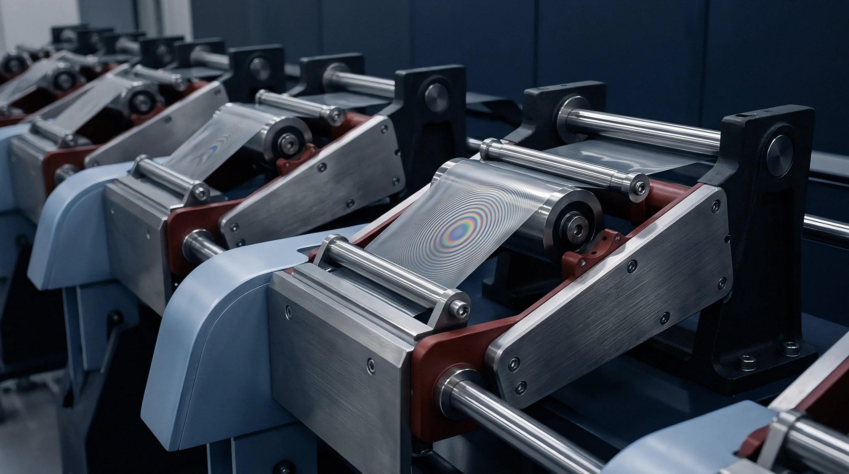
Integrating ultra-thin pouch cells into consumer electronics, aerospace structures, or medical instruments introduces severe mechanical packaging challenges. In a typical smartphone or handheld industrial terminal, the battery compartment shares mechanical boundaries with display backplates, midframe structural ribs, and exterior cover glass. Structural deflection of the housing under battery expansion forces degrades ingress protection seals, breaks display adhesive bonds, and induces touch-panel distortion.

Will Silicon Blends Break Thin Enclosures?
Consider a practical engineering construction: a modern thin-profile device incorporating a single pouch cell with active dimensions of 80 millimeters length, 60 millimeters width, and 2.80 millimeters initial thickness. The active face area equals 4,800 square millimeters (0.0048 square meters). The anode chemistry contains eight percent silicon oxide blended with artificial graphite, producing an estimated fifteen percent total volumetric expansion over five hundred cycles.
The enclosure allocates a nominal cavity depth of 3.20 millimeters, leaving 0.40 millimeters total clearance split between air gap and a 0.30-millimeter microcellular foam pad.
| Operating State | Free Stack Thickness | Available Cavity Gap | Foam Strain Level | Resulting Clamping Force | Chassis Midpoint Deflection |
|---|---|---|---|---|---|
| Fresh Cell, 0% SOC | 2.80 mm | 0.40 mm | 0% | 0 N (0.00 MPa) | 0.00 mm |
| Fresh Cell, 100% SOC | 2.98 mm | 0.22 mm | 27% | 480 N (0.10 MPa) | 0.04 mm |
| 300 Cycles, 100% SOC | 3.15 mm | 0.05 mm | 67% (Densified) | 2,160 N (0.45 MPa) | 0.18 mm |
| 500 Cycles, 100% SOC | 3.28 mm | -0.08 mm (Interference) | 100% (Solid) | 5,760 N (1.20 MPa) | 0.42 mm |
| Assumes 0.8 mm magnesium-aluminum alloy midframe wall with fixed edge constraints and a 0.30 mm initial foam cushion thickness. | |||||
The calculations demonstrate how mechanical stiffness multiplies minor geometric miscalculations. By cycle 500, the active stack thickness exceeds the nominal cavity depth. The foam pad reaches solid densification, transferring 5,760 newtons (over 580 kilograms-force) into the midframe.
The resulting 0.42-millimeter midpoint deflection exerts severe bending moments on delicate display driver circuits located on the reverse side of the midframe wall.
Under-sizing the mechanical clearance causes display delamination, fractured cover glass, ruptured peripheral perimeter seals, and permanent housing deformation.

Stipulation
Controlling anode expansion forces requires explicit commercial and technical boundaries within cell supply contracts and engineering specifications. Procurement teams often purchase pouch cells based solely on standard electrical parameters: nominal capacity, charge cutoff voltage, discharge cutoff voltage, internal AC impedance, and cycle life to eighty percent capacity retention. Omitting mechanical swelling limits from the incoming inspection criteria leaves the pack integrator fully exposed to upstream design revisions.
Cell manufacturers regularly modify binder formulations, active material particle sizing, silicon doping ratios, and calendering densities to hit aggressive electrical capacity targets without updating published external dimensions. A change that increases capacity by five percent can double irreversible swelling forces over long-term cycling. Sourcing contracts must bind the supplier to tight physical growth tolerances alongside electrical performance metrics.
- Maximum swollen thickness callouts define the absolute allowable physical thickness at one hundred percent state of charge after eight hundred full cycles under a defined clamp pressure.
- Pressure-displacement test standards fix the precise platen geometry, measurement speed, thermal soak time, and load profile used during incoming lot qualification.
- Electrode overhang alignment limits establish strict geometric boundaries for anode-to-cathode edge overlap to prevent intense edge-stress concentrations under compression.
- Tooling revision notifications bind the cell supplier to provide ninety days written notice prior to altering anode slurry formulations, particle coatings, or calendering densities.
Engineering drawings must include a section view defining the constrained inspection state. The drawing note must reference a specific mechanical test fixture, specifying platen flatness within 0.02 millimeters, parallelism within 0.03 millimeters, and an applied measurement load of 0.10 megapascals. Unambiguous drawing notes eliminate disputes during incoming lot rejections.
Incorporating international standard IEC 61960-3 dimensional verification clauses into the master supply agreement establishes legal authority for rejecting shipments that exceed thickness tolerances at maximum state of charge.