Argon Gas Entrapment Mechanisms in Tool Steel Powder Atomization
Gas atomization parameters and nozzle delivery pressures dictate argon entrapment levels, governing melt superheat control and inert gas mass monitoring.


Plume

Gas Jet Dynamics and Droplet Breakup Mechanics
In high-pressure gas atomization, supersonic argon streams transfer kinetic energy to break liquid tool steel into fine droplets. Inside the upper chamber, this melt disintegration happens in two stages: primary breakup, where surface waves driven by Rayleigh-Taylor and Kelvin-Helmholtz instabilities shear the stream into thin liquid sheets and filaments, and secondary breakup, which rapidly shatters those filaments into spherical droplets before surface tension seals the metal boundary.
Operating parameters directly alter gas kinetic energy, shear stress in the liquid metal, and local cooling rates. High-alloy grades like AISI H13, M36, and CPM 10V have high molten viscosity and surface tension owing to heavy concentrations of carbide-forming elements like vanadium, molybdenum, and tungsten. When supersonic argon strikes the melt stream at delivery pressures between 2.5 MPa and 5.0 MPa, high-velocity gas boundary layers induce local pressure gradients around individual droplets.
Recirculation vortices just downstream of the breakup zone draw high-velocity gas pockets directly into the liquid filaments, which fold over the turbulent eddies and trap argon inside before the surface seals.
The gas-to-metal mass ratio (GMR) measures argon mass flow against liquid tool steel throughput. Raising the GMR increases atomization energy and yields finer mean particle sizes, but it also steepens local velocity gradients in the spray. Higher gas velocities boost turbulent kinetic energy in the primary breakup zone, expanding the liquid filament surface area vulnerable to vortex encapsulation.
Argon concentration in gas-atomized tool steel powder increases from 0.8 ppm to 4.2 ppm by weight when the gas-to-metal ratio rises from 1.2 to 2.8 at 4.5 MPa delivery pressure.
Melt superheat dictates how long trapped argon bubbles have to escape before freezing. Higher superheat lowers viscosity and delays surface solidification, giving buoyant argon micro-bubbles time to float toward the particle edge and vent into the chamber. Lower superheat forms a surface skin almost immediately, trapping gas bubbles before buoyancy can drive them out.

Vortex Capture in Primary Disintegration
In close-coupled nozzles, gas entrapment is largely driven by recirculation flows right beneath the delivery tip. As supersonic argon expands through the orifice, a low-pressure suction zone forms at the exit face of the feed tube. This pressure difference draws chamber gas back toward the exiting liquid stream, generating swirling toroidal vortex rings.
Molten tool steel encounters these vortices before it reaches peak atomization speed. Shear forces at the gas-liquid interface fold the outer layer of metal over the stagnant gas pockets, trapping argon into continuous gas cores within thick liquid filaments. When these filaments shatter into smaller droplets, discrete internal gas pockets remain inside.
Unstable melt delivery pressure aggravates this effect, causing broad variations in internal gas concentration within a single production lot.
| Tool Steel Grade | Atomization Pressure (MPa) | Gas-to-Metal Ratio (GMR) | Melt Superheat (K) | Argon Content (ppm wt) |
|---|---|---|---|---|
| AISI H13 (1.2344) | 2.8 | 1.3 | 180 | 0.95 |
| AISI H13 (1.2344) | 4.2 | 2.4 | 180 | 3.10 |
| CPM 10V | 3.0 | 1.5 | 220 | 1.20 |
| CPM 10V | 4.8 | 2.7 | 220 | 4.85 |
| AISI M2 (1.3343) | 3.5 | 1.8 | 160 | 2.40 |
| Data recorded via LECO inert gas fusion combined with mass spectrometry; samples screened below 53 micrometers. | ||||
Whether micro-turbulent eddies in the primary breakup zone can be suppressed entirely through convergent-divergent nozzle profiling without destabilizing the melt stream remains an open question in high-alloy powder production.


Pore

Core-Shell Particle Morphology and Satellite Collisions
The structure of internal gas cavities in atomized tool steel depends on where they form inside the spray chamber. Descending droplets face extreme cooling rates between 10,000 K/s and 100,000 K/s, so fine droplets freeze almost instantly while larger ones stay semi-molten during flight. Speed differences between fine and coarse particles lead to collisions in the turbulent flight zone below primary breakup.
Satellite attachment happens when fully solid fine particles strike larger, semi-molten droplets. These high-speed impacts embed the fine particles into the soft liquid surface, splashing metal around the crater and trapping chamber argon in the tight angles around the contact interface. If the liquid metal completely engulfs the satellite, the trapped gas pocket gets buried deep inside the droplet, creating a core-shell morphology with off-center voids.
Solubility rejection during rapid solidification provides another pathway for gas inclusion. Argon has negligible equilibrium solubility in molten iron and virtually none in solid ferrite or austenite. High atomization pressures temporarily force trace argon into the liquid at high temperatures, but as the droplet cools past the liquidus, rapid dendritic growth pushes the gas out into the remaining liquid pockets.
Trapped inside a rigid solid shell, the contracting liquid starves, allowing nucleated argon to expand into spherical interdendritic micro-voids.
Satellites adhering to liquid droplets during flight seal turbulent gas pockets inside the solidifying sphere long before the powder reaches the collection hopper.
Defects arising from gas entrapment vary in structural geometry and spatial distribution across atomized powder lots:
- Satellite Encapsulation occurs when solid fine particles hit semi-molten droplets, trapping spherical argon pockets beneath the surface along internal boundary zones.
- Dendritic Gas Trapping happens during rapid solidification as rejected argon nucleates in contracting interdendritic spaces inside the particle core.
- Vortex Bubble Insertion forms large central cavities inside coarse powder particles when liquid sheets fold over during primary breakup.
- Recirculation Cap Capture occurs as fine satellite dust re-enters the primary plume, coating larger droplets in micro-porous oxide-gas layers.

Analytical Techniques for Gas Void Quantification
Standard pycnometry measures skeletal volume through gas displacement, but it misses closed internal pores that do not reach the particle surface. Optical metallography on polished cross-sections reveals two-dimensional void patterns, but it tends to underestimate total gas volume because of sectioning bias and polishing relief around hard carbide phases.
X-ray micro-computed tomography (XCT) provides non-destructive 3D visualization of internal structures down to 0.5 micrometer spatial resolution. High-resolution scans separate spherical gas-driven voids from irregular shrinkage porosity by filtering for sphericity factors above 0.85, yielding total internal void volume fractions, pore size distributions, and spatial orientation within individual grains.
| Measurement Method | Detection Limit | Sample Size | Destructive Test | Primary Measurement Output |
|---|---|---|---|---|
| Inert Gas Fusion LECO | 0.01 ppm wt | 1.0 gram | Yes | Total bulk argon concentration mass fraction |
| X-Ray Micro-CT Scan | 0.5 micrometer pore size | 0.1 gram | No | 3D pore volume distribution and morphology |
| Helium Pycnometry | 0.01 percent density | 10.0 grams | No | Skeletal density excluding closed porosity |
| Optical Cross-Sectioning | 1.0 micrometer pore size | 5.0 grams | Yes | 2D area fraction and void shape factors |
Inert gas fusion combined with quadrupole mass spectrometry gives precise chemical measurements of total bulk argon. Powder samples are melted in a high-purity graphite crucible inside an impulse furnace, releasing trapped argon into a helium carrier stream. The gas passes through chemical scrubbers into a mass spectrometer calibrated with noble gas reference standards, capturing total argon whether it sits in primary cavities, satellite interfaces, or surface adsorbates.
Powder batches with heavy satellite attachment on particle surfaces consistently show higher residual gas levels than smooth, spherical lots.


Void

Why Does Gas Pore Expansion Reappear during Austenitizing?
Consolidating atomized tool steel through hot isostatic pressing subjects internal gas pockets to intense hydrostatic stress. Under typical HIP conditions ~ 1150°C and 100 MPa to 150 MPa ~ the yield strength of the matrix drops sharply, forcing metal to yield plastically around internal pores and collapsing spherical cavities via power-law creep and dislocation climb.
As heat and compression force closing pore walls together, solid-state diffusion bonds them shut. Because argon cannot diffuse into the iron crystal lattice or form stable compounds with alloy elements, trapped gas molecules have no way out. Hydrostatic pressing squeezes this trapped gas into ultra-high-pressure micro-pockets along prior particle boundaries or inside grain interiors, shrinking pore diameters from tens of micrometers down to sub-nanometer scale and driving internal pressure above hundreds of megapascals.
Subsequent heat treatment disrupts this metastable pressure balance. High-carbon tool steels require austenitizing cycles between 1020°C and 1080°C to dissolve carbides before quenching and tempering. Reheating components lowers matrix yield strength while gas pressure inside the micro-pockets climbs with temperature.
Once internal gas pressure exceeds local matrix strength, thermally induced porosity (TIP) occurs as expanding argon pockets push outward, deforming the surrounding austenite matrix and reopening micro-voids.
ASTM B923 compliance testing catches density discrepancies from gas entrapment before tool steel powder enters hot isostatic pressing cans.
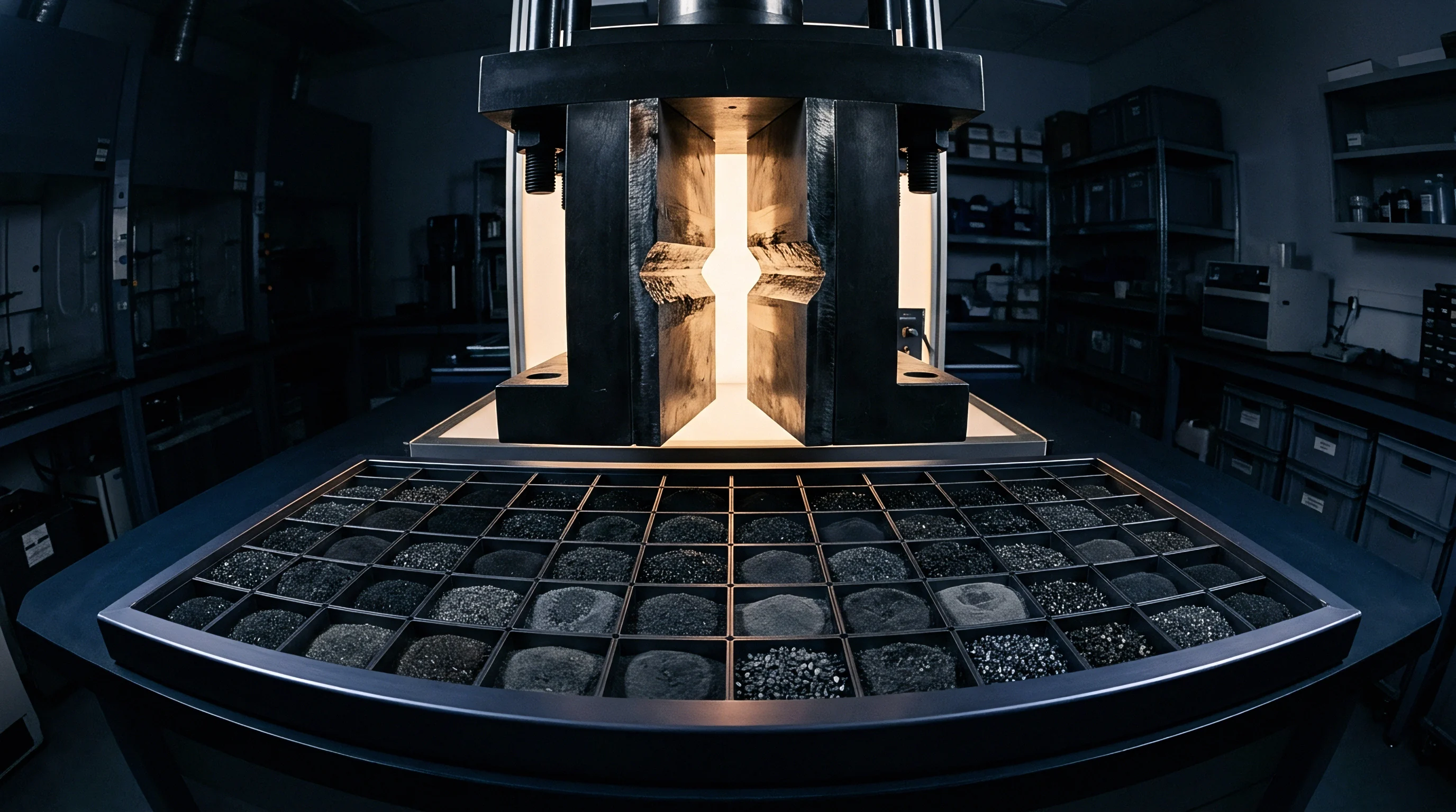
Mechanics of Thermal Induced Porosity in Hot Isostatic Pressing
Reopened gas voids weaken consolidated tool steels by acting as stress concentrators under cyclic loading, which accelerates fatigue crack initiation in dies. Impact toughness drops alongside this rise in void fraction, sharply reducing Charpy V-notch energy absorption in hardened components.
Evaluating thermally induced porosity propensity in consolidated tool steel billets follows a structured testing sequence:
- Machining ten cylindrical test specimens measuring 10 mm in diameter and 15 mm in height from the consolidated powder billet core.
- Measuring initial specimen density using Archimedes immersion testing in distilled water at 20°C per ASTM B962 guidelines.
- Subjecting test specimens to vacuum thermal exposure at 1150°C for 24 hours inside a high-purity quartz furnace tube held at pressures below 0.001 Pa.
- Re-measuring post-exposure bulk density to determine total density degradation caused by gas bubble expansion.
- Examining polished cross-sections under scanning electron microscopy to calculate the expanded pore area fraction and mean void diameter.
In high-stress hot-work dies subject to rapid thermal cycles, thermally induced porosity degrades tool life by accelerating premature thermal fatigue cracking from expanding internal voids.
Unchecked argon accumulation leads to micro-cracking during heat treatment, causing premature die failure and wasted machining costs.

Nozzle
Close-Coupled Architecture versus Free-Fall Systems
The mechanical design of the melt exit interface sets the fluid dynamic boundaries between the gas stream and liquid steel. Free-fall atomizers place the gas ring several hundred millimeters below the crucible orifice, letting liquid metal fall under gravity as an unconstrained stream before hitting convergent supersonic jets. This setup minimizes gas interaction at the tip, reducing aspiration pressure differentials and entrapment risks, but yields coarse powder unsuitable for laser powder bed additive manufacturing.
Close-coupled nozzles place gas exit orifices right next to the ceramic melt delivery tip. Gas jets hit the liquid stream within millimeters of exit, imparting peak kinetic energy before the stream can spread. While close-coupled geometry maximizes powder yield in fine cuts below 53 micrometers, it creates steep aspiration pressure differentials across the delivery tip face.
High-velocity gas expansion creates a suction zone at the base of the ceramic tip. This negative pressure draws chamber atmosphere upward against molten metal flow, disturbing stream convergence. If pressure drops below critical thresholds, supersonic gas bubbles penetrate the melt exit orifice, causing violent splashing and drawing high levels of argon into the primary stream before breakup even begins.
Melt Delivery Tube Hydrodynamics and Pressure Balance
Precision engineering of melt delivery tip profiles stabilizes gas flow fields around the liquid orifice. Tapered ceramic tips angled to match the internal gas ring convergence limit boundary layer separation, lowering static suction pressure where metal exits.
Controlling melt tube geometry and operational parameters suppresses internal gas entrapment across atomization production runs:
- Delivery Tip Recess controls the vertical offset between the melt tube and gas ring exit plane, altering local static pressure boundaries.
- Manifold Pressure Uniformity prevents circumferential flow variations that cause asymmetric shearing and localized bubble capture.
- Gas Jet Impingement Angle optimizes kinetic energy transfer while minimizing upward gas reflection against the liquid delivery tip face.
- Plexus Degassing Purge replaces high-pressure chamber argon with volatile purge gases prior to melt release to reduce inert bubble persistence.
Swirl nozzles alter plume boundary turbulence by adding rotational velocity to expanding argon jets. Rotational shear destabilizes stagnant toroidal vortices at the delivery tip exit, dispersing gas pockets before droplets freeze. However, swirl geometry increases gas consumption per kilogram of atomized steel, raising operating costs over long production runs.
Minor internal gas voids close during hot isostatic pressing, leaving no structural defects in finished tooling.
Receipt
Sourcing Specifications and Argon Threshold Verification
Procurement contracts for tool steel powders define physical and chemical acceptance criteria to guard against latent defects. Organizations setting quality standards for additive manufacturing or hot isostatic pressing need strict upper limits on residual inert gas. Certificate of Analysis (CoA) documentation from powder atomizers routinely leaves out noble gas metrics unless purchase orders explicitly require them.
Argon limits depend on application criticality. Premium powders for high-cycle forging dies, critical inserts, or aerospace structural parts require bulk argon levels under 0.5 ppm by weight. Standard commercial grades for press-and-sinter or non-critical mold components tolerate thresholds up to 2.5 ppm by weight.
Including explicit analytical protocols in purchasing agreements avoids disputes over sample preparation and mass spectrometer calibration.
Thermal induced porosity expands closed argon pockets into micro-cracks during high-temperature austenitizing treatments.

Commercial Acceptability Windows and Contractual Quality Limits
Verification requires representative lot sampling before powder containers are accepted. Sampling per ASTM B215 harvests increments across multiple container depths to account for density and particle segregation across a batch. Lots that fail chemical gas limits add directly to incoming yield losses.
| Application Grade | Target Tool Steel Types | Max Argon Content (ppm wt) | Max Thermally Induced Porosity (Vol %) | Sphericity Index Minimum |
|---|---|---|---|---|
| Aerospace & High Cycle Tooling | CPM 10V, Vanadis 4E | 0.50 | 0.02 | 0.90 |
| Die Casting & Hot Work | AISI H13 (1.2344) | 1.00 | 0.05 | 0.88 |
| Cold Work Standard Dies | AISI D2, AISI M2 | 2.00 | 0.12 | 0.85 |
| General Structural PM | 1.2709 Maraging Steel | 3.50 | 0.25 | 0.82 |
Rejecting non-compliant powder before consolidation avoids compounding downstream machining and heat treatment costs. Material specifications ought to define financial remedies when powder causes thermally induced porosity during secondary processing. Binding suppliers contractually to verified gas limits ensures consistent performance across tool steel supply chains.
Adding an explicit thermal stability clause based on ASTM E2520 testing to purchase agreements shifts the financial loss of unviable powder batches back to the atomizer.