Meaning
Electrical testing methodologies utilize four separate conductive paths to eliminate the influence of lead wire impedance during resistance measurements. Kelvin 4-wire sensing operates by supplying a constant current through two outer leads while a separate pair of inner leads measures the voltage drop directly across the component. This separation of current delivery and voltage detection ensures that the resistance of the cables themselves does not shift the accuracy of the reading.
Voltmeters within such configurations present high input impedance to prevent current from flowing through the detection circuit.
Measurement Accuracy
Precision instruments rely on this separation to quantify milliohm values without introducing error from contact resistance at the probe interface. Standard two-wire setups include the resistance of the test leads within the total measurement, which creates significant variance when measuring low-resistance cells or busbars. By isolating the voltage sense path from the current injection path, the technician receives an authentic assessment of the hardware properties rather than the connection stability.
High-current environments require this isolation to maintain calibration during thermal expansion or mechanical vibration.
System Application
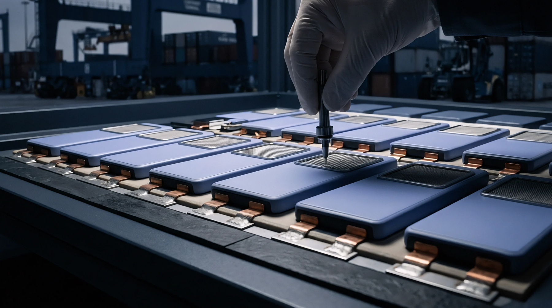
Battery management platforms incorporate these circuits to monitor internal cell resistance as an indicator of electrochemical health. Automated production lines deploy these configurations to verify weld quality on tab connections during final assembly. Integrating such circuits allows a charger or a battery cycler to compensate for the distance between the measurement electronics and the energy storage unit.
Effective grounding strategies ensure that no potential difference exists between the reference nodes during high-speed data acquisition.
Operational Boundary
Environmental factors such as electromagnetic interference influence the signal integrity of the sensing lines if they remain unshielded. Long distance runs between the device under test and the measurement hardware induce parasitic inductance, which necessitates the use of twisted pair cabling to cancel out external field coupling. Proper maintenance of the contact surface between the four pins and the terminal prevents open circuit conditions during automated testing.
Consistent probe pressure ensures that the current remains stable throughout the entire duration of the measurement cycle.