Correlation between Quantitative Stereological Carbide Banding Parameters and Die Fatigue Life under Cyclical Impact Loading
Carbide banding anisotropy above 1.5 accelerates cleavage fracture under cyclic impact, reducing cold-work die service life by over 60 percent.

Notch
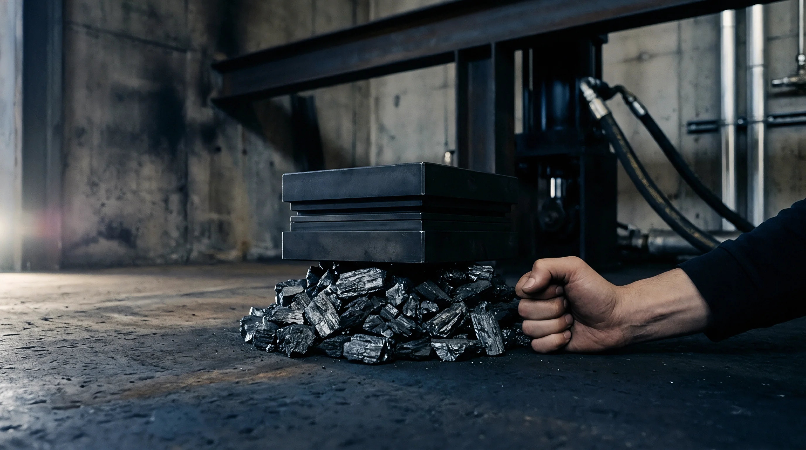
Primary eutectic carbide clusters in cold-work tool steels act as localized stress raisers under repetitive mechanical shock. Blanking high-nickel battery cathode foils subjects cutting punches to rapid compressive strikes that rebound into severe surface tension. When chromium or vanadium carbides segregate into planar bands, elastic modulus mismatches between the brittle particles and the tempered martensitic matrix create active microcrack initiation sites.
Cleavage planes across these particles open flaws well below the bulk steel’s nominal yield threshold, while continuous particle lanes in mill-annealed stock focus cyclic plastic strain onto narrow matrix ligaments.
Die life drops sharply when carbide stringers lie perpendicular to principal cyclic tensile stresses. In conventional ingots, dendritic segregation concentrates alloying elements like chromium, molybdenum, and tungsten in the residual melt between dendrite arms. Subsequent hot reduction by forging and rolling draws these solute-rich zones into directional bands along the primary working axis.
Coarse primary carbides that precipitate in these bands resist dissolution during austenitizing heat treatments.
Brittle particle stringers oriented perpendicular to dynamic tensile stresses cut die strike endurance by more than half compared to isotropic particle dispersions.
Tool failure under impact fatigue follows a recognizable progression. Microcracks initiate at the particle-matrix interface by decohesion, or cleave directly across large primary carbides during early load cycles. These initial flaws then push across adjacent matrix bridges, joining along the carbide band into macroscopic crack fronts.
Once a macrocrack reaches critical size, dynamic loads drive rapid fracture through the remaining section, causing catastrophic cutting edge spallation.
Orientation determines whether an internal crack stalls or runs. Carbide bands aligned parallel to the punch trajectory force growing flaws to exit brittle clusters and work through ductile matrix regions. Transverse bands, by contrast, present contiguous low-energy cleavage paths that propagate cracks with minimal plastic dissipation.
When billet grain direction is misaligned with punch strike vectors, cutting edges can crumble within the first thousand stamping cycles.

Cleavage Mechanics across Segregated Alloy Bands
Dynamic impact generates strain rates above one thousand per second along the perimeter of cold-forming punches. At these rates, dislocation mobility in the tempered martensitic matrix drops sharply, suppressing local plastic stress relaxation at carbide boundaries. Clustered angular carbides act as internal notches, focusing high dynamic stresses right at the particle interfaces.
The stress concentration factor at the pole of an isolated primary carbide scales with the square root of its major axis divided by the tip radius. In segregated steels, neighboring particles interact elastically to intensify the peak stress in the intervening matrix ligament. Once the distance between carbides falls below one particle diameter, their stress fields merge completely, raising local matrix stress to three times the applied macroscopic level.
- Interfacial Decohesion occurs predominantly along smooth carbide interfaces when cyclical shear stresses exceed the interface bond strength.
- Intraparticle Cleavage dominates in coarse primary carbides exceeding five micrometers in diameter under high dynamic shock loads.
- Matrix Bridge Tearing develops between fractured particles through localized micro-void coalescence along the banding plane.
- Planar Crack Unification aligns multiple micro-fissures into an operational fatigue crack front traversing the entire die cross-section.
Fine, uniformly dispersed secondary carbides distribute mechanical strain evenly through the microstructure during impact strikes.

Spacing
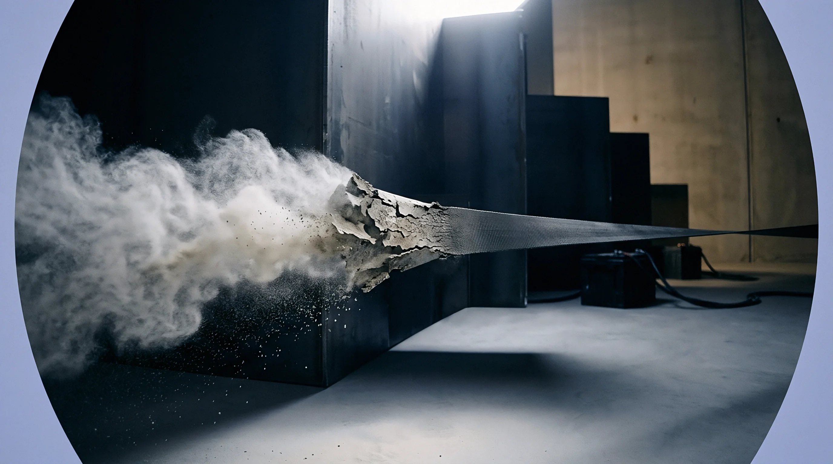
Linear intercept measurements quantify how alloy carbides are distributed across forged tool steel blocks. Quantitative metallography uses planar cross-sections polished both parallel and perpendicular to the billet reduction axis to calculate stereological parameters. ASTM E1268 testing protocols define metrics such as mean band width, band center-to-center spacing, and the degree of orientation, giving microscopic observations a reproducible numerical basis.
Mean band spacing reflects the average distance between adjacent carbide-dense regions on a metallographic section. A high spacing value with narrow band widths indicates isolated segregation lanes buffered by broad spans of uniform matrix. Low spacing with thick bands, conversely, points to heavy microstructural clustering that compromises shock resistance.
Standard ASTM E1268 anisotropy ratings above two point five correspond to tool fatigue life reductions exceeding sixty percent under cyclical shock loading.
Carbide volume fractions inside segregated bands differ sharply from bulk assays. Bulk AISI D2 contains roughly twelve to fourteen percent total carbide by volume, but local volume fractions within stringers regularly reach thirty-five percent. This local crowding displaces matrix material and leaves too little ductile volume to blunt advancing microcracks.
| Steel Grade And Melting Route | Mean Band Spacing (µm) | Carbide Volume Fraction In Band (%) | Anisotropy Index | Mean Free Path In Matrix (µm) |
|---|---|---|---|---|
| AISI D2 Conventional Cast | 42.5 ± 6.2 | 34.2 ± 3.8 | 2.85 ± 0.30 | 1.8 ± 0.4 |
| AISI D2 Electroslag Remelted | 68.0 ± 5.1 | 22.5 ± 2.4 | 1.65 ± 0.15 | 3.9 ± 0.5 |
| AISI M2 Conventional Cast | 35.0 ± 4.8 | 38.0 ± 4.1 | 3.10 ± 0.35 | 1.2 ± 0.3 |
| AISI M2 Electroslag Remelted | 58.5 ± 4.5 | 25.0 ± 2.6 | 1.80 ± 0.18 | 3.2 ± 0.4 |
| Vanadis 4 Extra Powder Metallurgy | 0.0 ± 0.0 | 14.5 ± 1.2 | 1.02 ± 0.03 | 6.5 ± 0.6 |
Mean free path measures the uninterrupted span of tempered martensite between neighboring carbide particles. It defines the physical room available for dislocation glide and plastic zone expansion at a crack tip. When the carbide mean free path drops below two micrometers, cyclic micro-yielding quickly exhausts the limited ductility of the matrix.

Which Segregation Metric Correlates with Cleavage Initiation?
The carbide contiguity ratio measures particle-to-particle contact area relative to total particle surface area. Clean powder metallurgy steels maintain contiguity values below zero point zero five, indicating nearly all carbides sit isolated in the matrix. In heavily banded ingot-cast alloys, contiguity along stringers often exceeds zero point four zero.
High contiguity provides a continuous ceramic path for cleavage cracks to run without encountering energy-absorbing metallic ligaments.
Determining the true three-dimensional mean intercept length requires stereological conversion from two-dimensional polished sections. Planar cuts consistently underestimate grouping because random cross-sections intersect particles off-center. Saltykov stereological unfolding algorithms correct for these planar sectioning effects, converting measured intercepts into accurate volumetric distributions across the steel matrix.
Whether secondary carbide precipitation during multiple tempering cycles alters the effective mean free path sufficiently to mitigate primary eutectic banding remains unresolved across tool steel metallurgy literature.


Impulse
During high-velocity stamping, striking energy transfers from the punch face into the internal grain structure within microseconds. Mechanical presses cycling at four hundred strokes per minute expose die tips to steep rise-time shock profiles. Blanking current collector foils coated with abrasive lithium metal oxides subjects punch perimeters to mixed loading: severe compressive impact followed immediately by lateral shear and high-frequency rebound tension.
Compressive stress waves reflect off acoustic impedance boundaries in the tool mounting assembly, converting into tensile spikes. When a tensile wave strikes a plane of segregated carbides oriented normal to its propagation path, it sets up dynamic mode-I opening stresses across the brittle particles. In banded microstructures with high contiguity, these reflected tensile impulses routinely exceed the dynamic cleavage strength of the carbides.
Repetitive shock produces cumulative low-cycle micro-plastic fatigue in punch profiles. In high-volume electrode production, tools must run tens of millions of strokes without chipping. Micro-yielding accumulates in the matrix ligaments between banded carbides on each cycle, developing dislocation cell structures that eventually rupture into voids.
Dynamic striking pulses transform into destructive tensile reflections whenever acoustic boundaries interrupt compressive wave propagation through the die body.
Strain rate sensitivity separates cyclic impact fatigue from standard rotating-bending fatigue behavior. Conventional S-N curves established at low cyclic frequencies misjudge die life because high strain rates increase yield strength while sharply reducing dynamic fracture toughness. A grade showing acceptable static toughness can chip without warning under high-frequency impulses in production presses.
| Tool Steel Type And Hardness | Banding Orientation To Impact Axis | Mean Impact Cycles To Edge Chipping | Dynamic Fracture Toughness KId (MPa√m) |
|---|---|---|---|
| Conventional D2 (60 HRC) | Transverse (90 Degrees) | 142,000 ± 18,000 | 16.5 ± 1.2 |
| Conventional D2 (60 HRC) | Longitudinal (0 Degrees) | 385,000 ± 32,000 | 22.4 ± 1.5 |
| Electroslag D2 (60 HRC) | Transverse (90 Degrees) | 410,000 ± 29,000 | 21.8 ± 1.4 |
| Electroslag D2 (60 HRC) | Longitudinal (0 Degrees) | 760,000 ± 45,000 | 28.2 ± 1.8 |
| Powder Metallurgy D2 (60 HRC) | Isotropic (Any Angle) | 1,850,000 ± 95,000 | 36.5 ± 2.1 |

Dynamic Peak Stresses in Battery Calendering and Punching
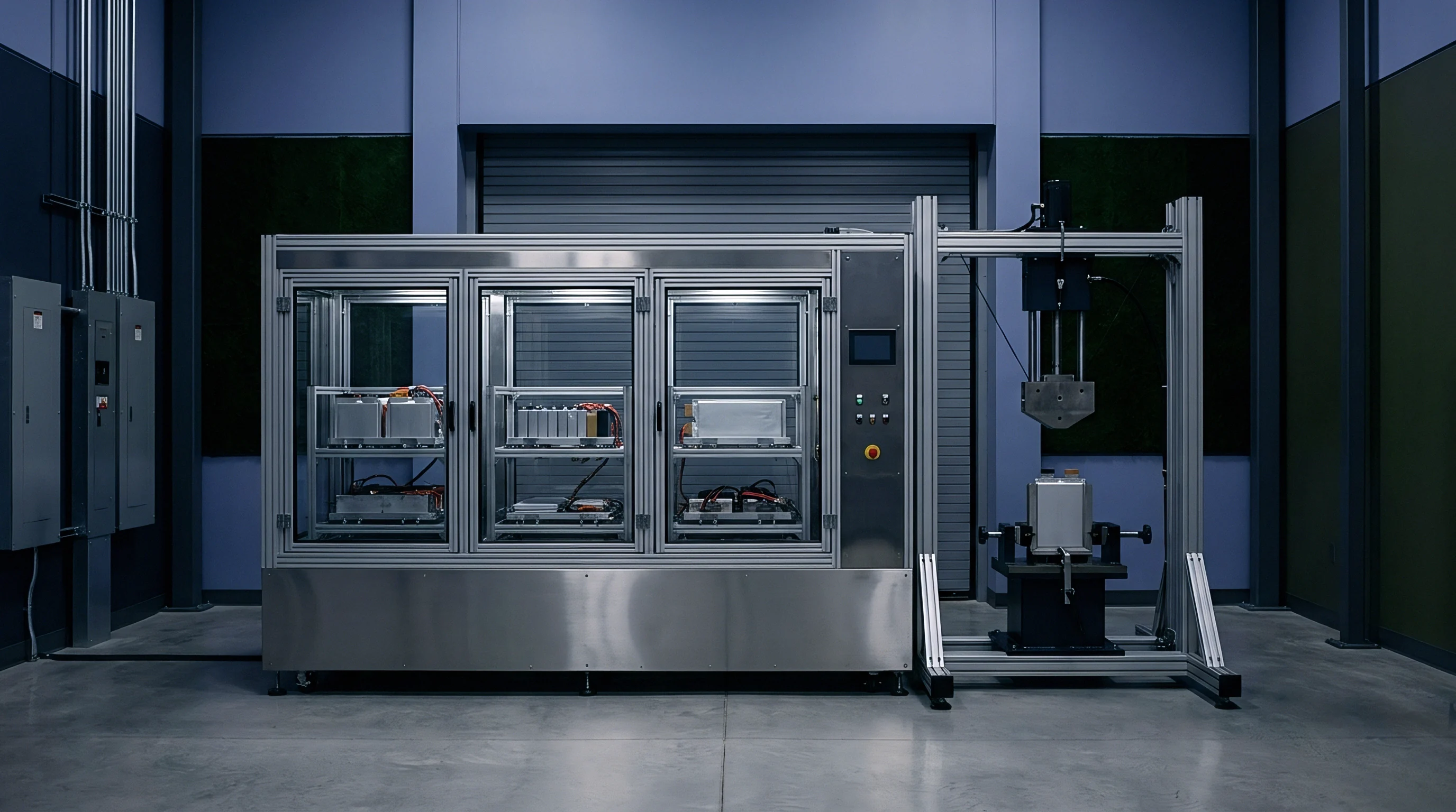
Electrode cutting dies encounter distinct localized stress profiles from the abrasive nature of slurry coatings. High-speed slitting of double-sided cathode foil forces the punch edge through brittle lithium nickel manganese cobalt oxide particles before it shears the aluminum substrate. Abrasive contact leaves surface notches that work alongside subsurface carbide banding to accelerate fatigue spallation.
Finite element modeling of cyclic stamping indicates that peak tensile stresses develop roughly fifty to one hundred micrometers behind the primary cutting edge radius. In conventionally cast tool steels, this zone coincides with the depth of typical eutectic carbide segregation lanes. Placing segregated stringers inside this dynamic tension band reliably produces premature chipping.
High core hardness does not compensate for microstructural directional banding under high-speed industrial stamping presses.

Propagation
Fatigue crack progression through heterogenous tool steel microstructures follows the path of least resistance. When a microcrack initiates via particle cleavage in a carbide-dense stringer, its trajectory depends on the spacing and orientation of adjacent particles. If a neighboring carbide falls within the cyclic plastic zone ahead of the crack tip, the crack jumps forward, cleaving the particle before fully shearing the intervening matrix.
Linear elastic fracture mechanics models this behavior through effective stress intensity ranges. In homogenous matrix zones, crack growth rates track Paris Law relationships where cyclic advance depends on the stress intensity range exponent. Inside dense carbide bands, cracks accelerate locally because brittle intraparticle cleavage advances the crack front without consuming plastic deformation energy.
Carbide stringers eliminate crack-tip plastic blunting by promoting rapid brittle cleavage through connected alloy networks.
Microcrack coalescence governs overall fatigue life under impact loading. Instead of a single flaw traversing the tool, hundreds of isolated microcracks nucleate concurrently along segregated bands. Once cyclic stresses reach a critical threshold, these distributed defects join through sudden shear localization in the matrix, triggering extensive spalling.
- Primary carbide cleavage initiates across particles larger than eight micrometers during initial high-strain cycles.
- Matrix plastic exhaustion occurs across intervening narrow metallic ligaments under ongoing impact vibrations.
- Secondary crack branching tracks interconnected stringer paths, bypassing tougher surrounding matrix areas.
- Unstable shear instability connects coplanar micro-defects into an open, continuous macroscopic fracture network.
- Total edge spallation detaches working tool sections, ending productive tool life and damaging production assemblies.
Crack arrest mechanisms require the crack front to encounter wide zones of ductile matrix. High carbide mean free paths force advancing cracks to blunt their tips by emitting dislocations into the tougher tempered martensite. This blunting absorbs dynamic strike energy and lowers fatigue crack growth rates by orders of magnitude.

Microstructural Anisotropy and Crack Path Deflection
Carbide bands create pronounced directional differences in fracture resistance. A fatigue crack travelling parallel to the banding plane moves quickly along a smooth path with low fracture surface roughness. In contrast, transverse crack growth forces the front to bend and branch continuously as it crosses alternating hard and soft layers.
Crack deflection increases macroscopic fracture energy by lowering the effective local mode-I stress intensity at the tip. Deflecting a crack out of its principal loading plane introduces mode-II and mode-III shear components that absorb additional mechanical work. In banded steels, this toughening mechanism operates only when impact forces drive cracks across the bands rather than along them.
Premature punch fracturing from carbide stringers halts automated battery cell assembly lines, producing extensive downtime, unfulfilled delivery contracts, and scrapped electrode reels.


Allowance
Procurement specifications for impact tooling materials require quantitative stereological limits to avoid early tool failures. Bulk hardness testing and chemical mill test reports alone do not reveal severe microstructural banding. Premium cold-work dies for critical battery component blanking require strict incoming inspection covering maximum primary carbide size, mean band spacing, and anisotropy.
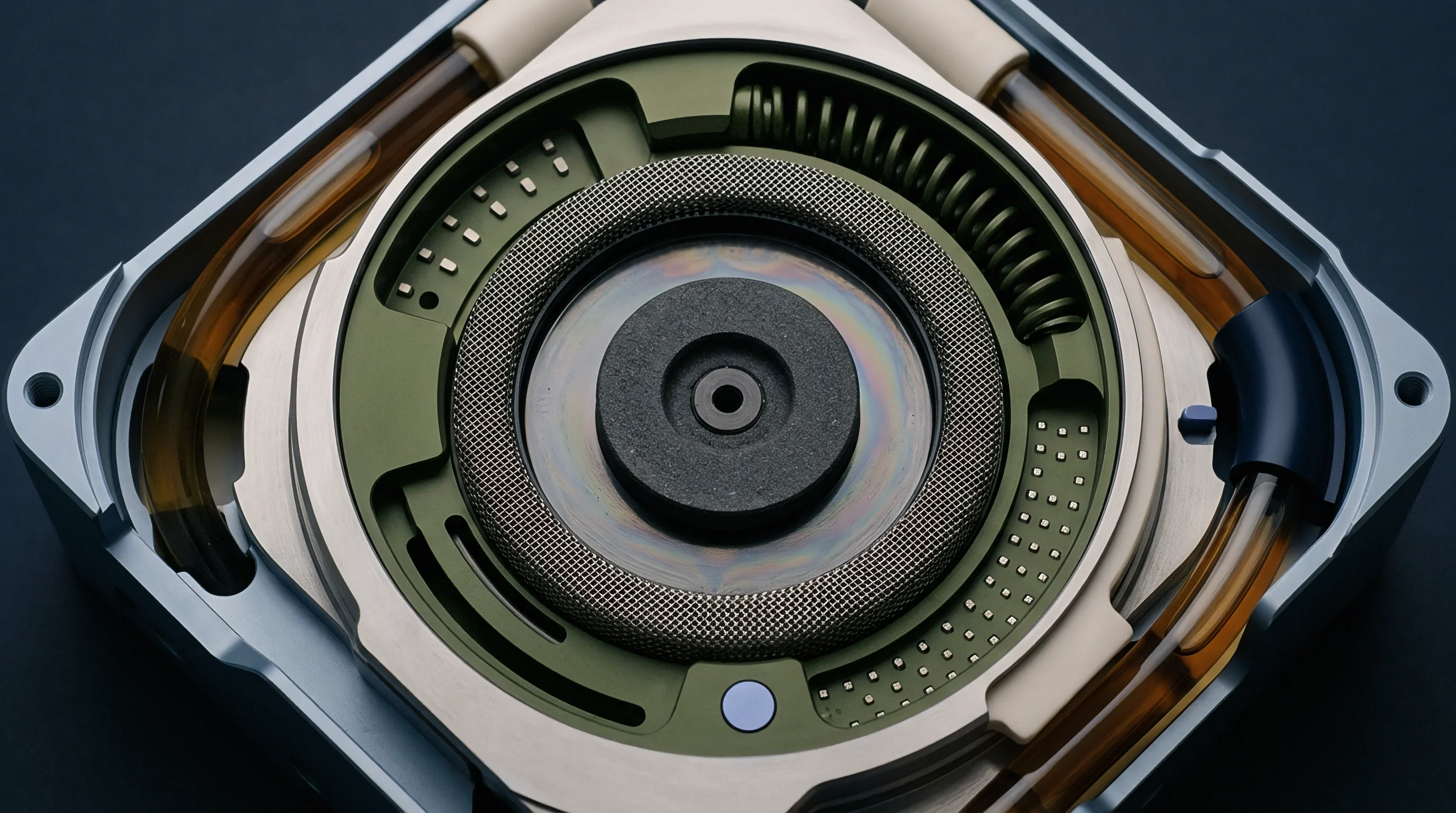
Billet inspection standardly relies on metallographic samples taken from core and mid-radius locations on forged rounds and flats. Polished sections etched with four percent picral or Murakami reagent show the distribution of primary and secondary carbides under optical or scanning electron microscopes. Digital image analysis systems then measure stereological parameters across fifty random fields of view to ensure statistical validity.
Electroslag remelting and powder metallurgy are the two main production methods used to suppress carbide segregation. Electroslag remelting promotes progressive solidification in a water-cooled copper mold, refining dendrite arm spacing and limiting alloy element partitioning. Powder metallurgy avoids macro-segregation altogether by gas-atomizing molten steel into micron-sized spherical droplets that solidify rapidly, preserving a uniform alloy distribution.
| Microstructural Parameter | Conventional Ingot Cast (AISI D2) | Electroslag Remelted (ESR D2) | Powder Metallurgy (CPM 1V / 3V) |
|---|---|---|---|
| Maximum Primary Carbide Size | ≤ 25.0 µm | ≤ 12.0 µm | ≤ 3.0 µm |
| ASTM E1268 Degree of Banding | ≤ 0.65 | ≤ 0.35 | ≤ 0.05 |
| ASTM E1268 Anisotropy Index | ≤ 2.20 | ≤ 1.45 | ≤ 1.05 |
| Minimum Mean Free Path | ≥ 2.0 µm | ≥ 4.0 µm | ≥ 7.0 µm |
| Maximum Area Fraction in Bands | ≤ 30.0 % | ≤ 18.0 % | ≤ 12.0 % |
Raw material prices differ considerably across these melting routes. Powder metallurgy tool steels typically cost four to five times more per kilogram than conventional ingot-cast alloys. Calculating tooling costs on a per-million-punched-parts basis, however, alters the economic calculation.
Dies produced from homogenous, unbanded PM stock consistently achieve five to ten times the service life under dynamic impact, reducing unscheduled press downtime.
Whose Acceptance Limit Governs Ingot Centerline Banding?
Purchase orders must define explicit microstructural rejection thresholds directly on engineering drawings and procurement contracts. Tool steel distributors often dispute banding claims by citing broad national material specifications that contain no quantitative stereological criteria. Without explicit contract clauses enforcing ASTM E1268 limits, buyers carry the financial risk of dies failing from microstructural segregation.
Clear receiving protocols protect tooling budgets and production schedules. Quality teams should evaluate incoming billet lots through metallographic sampling before releasing stock to CNC machining, wire EDM, and heat treatment. Detecting segregation flaws at receiving prevents investing machining hours into tool steel that will crack on the press line.
Purchase contracts incorporating strict ASTM E1268 Anisotropy Index ceilings below one point five permit immediate rejection of incoming tool steel lots without supplier restocking penalties.