Solid State Module Spring Plate Compression Allowances under Cycling
Solid state spring plate allowances absorb 10 to 18 percent cell volumetric strain while bounding contact pressure between 1.0 and 4.0 MPa across cell life.
Stroke
Solid-state pouch cells with lithium metal anodes change dimensions significantly during charge and discharge. Plating metallic lithium at the anode-electrolyte interface produces macroscopic thickness expansion proportional to transferred aerial capacity, while stripping lithium during discharge contracts the stack ~ a dynamic breathing motion that module enclosures must accommodate.
Anode Volumetric Breathing Mechanics
Solid electrolytes eliminate volatile liquid solvents, but they require constant mechanical pressure to keep ionic pathways open. In sulfide-based architectures, lithium plating expands cell thickness by roughly 15 to 25 micrometers for every 10 milliamp-hours per square centimeter of cycled capacity. Silicon-dominant anode blends swell by more than 300 percent at the material level, causing a 12 to 18 percent bulk cell thickness increase at high state of charge.
Without restraint, this expansion leaves microscopic voids at the solid electrolyte interface during stripping.
Without adequate external clamping, mechanical separation occurs between the solid electrolyte separator and the alkali metal layer, causing localized resistance spikes, current concentration, and accelerated dendrite nucleation.
Sulfide-based solid-state pouch cells operating at 2.5 MPa constant clamping pressure retain 88 percent capacity over 1,500 continuous cycles.
Phase Transformations and Interfacial Pressure Thresholds
Keeping solid-solid contact across electrochemically active boundaries stops dendrite growth and current focusing. Sulfide electrolytes require at least 1.0 MPa of pressure to avoid losing contact at the interface, but pressure must stay under 5.0 MPa to prevent short circuits from lithium creeping into grain boundaries. Oxide-based solid electrolytes can take higher loads up to 15.0 MPa, though they offer almost no compliance under localized stress.
Module integration designs place compressible spring plates next to endplates or interleaved between cell pairs to absorb this periodic stroke. Mechanical design allowances account for both elastic expansion in active layers and cumulative plastic growth over hundreds of deep discharge cycles. Capacity loss over time may stem from spring plates failing to maintain baseline pressure rather than electrochemically driven interface degradation.

Load
Managing large dimensional shifts across cycles requires structural components that can absorb displacement without exceeding maximum force limits. Spring plates inside module housings convert stiff cell expansion forces into manageable spring rate curves, protecting pouch seals and frame bolts from mechanical over-stressing.
Spring Plate Topology Mechanics
Wave washers, Belleville disc stacks, and profiled leaf springs give distinct stroke-versus-force profiles in tight module enclosures. Wave spring plates deliver high force within shallow axial heights, making them useful in narrow slots between cells. Profiled leaf plates stamped from high-tensile spring steel provide predictable linear force gradients across wider displacement ranges, accommodating multi-millimeter cell expansion.
| Spring Topology | Axial Thickness (mm) | Stroke Capacity (mm) | Stiffness Profile | Mechanical Hysteresis (%) |
|---|---|---|---|---|
| Multi-Wave Steel Plate | 1.5 to 3.0 | 0.8 to 2.2 | Quasi-Linear | 3.0 to 5.0 |
| Belleville Washer Stack | 4.0 to 8.0 | 1.5 to 4.5 | Non-Linear Degressive | 6.0 to 10.0 |
| Stamped Leaf Spring Plate | 2.0 to 4.0 | 2.0 to 6.0 | Linear | 2.0 to 4.0 |
| Elastomeric Steel Hybrid Pad | 3.0 to 6.0 | 1.0 to 3.5 | Progressive Non-Linear | 12.0 to 18.0 |
Constant Force versus Variable Displacement Regimes
Linear stiffness profiles lead to widening stress ranges as cells thicken over time. A linear spring rate of 500 Newtons per millimeter adds 1,000 Newtons of load across a 2.0 millimeter expansion stroke, pushing cell stack pressure past electrochemical limits. Arranging Belleville washer stacks in series-parallel configurations provides a degressive spring rate, flattening force across middle displacement zones.
- Non-Linear Spring Stiffness Non-linear stiffness profiles cap peak mechanical stress on solid electrolyte interfaces at 100 percent state of charge.
- Mechanical Hysteresis Loops Energy dissipated during compression and relaxation cycles dampens mechanical shock, though it generates internal heat within damping pads.
- Volumetric Packing Efficiency Compact wave plate geometries reduce dead space inside the module, improving pack-level volumetric energy density.
Selecting spring plates with non-linear force-deflection plateaus prevents mechanical over-compression while maintaining baseline contact pressure across full discharge depth.

Fatigue
Repeated compression and relaxation degrade high-tensile spring steel alloys over time. Dynamic mechanical loads during charge-discharge cycles cause stress relaxation, lower yield strength, and risk fatigue micro-cracking over a vehicle’s operating life.
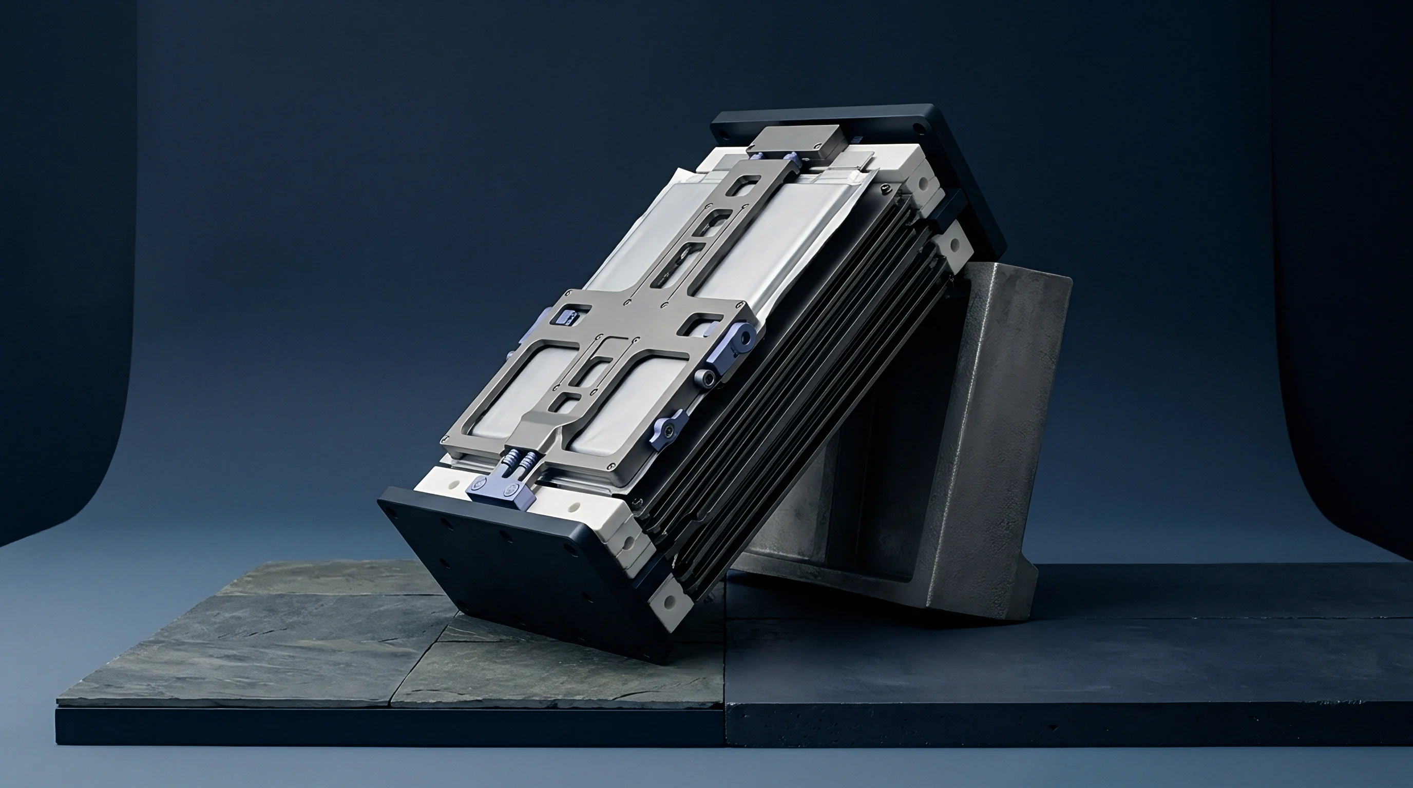
Which Spring Plate Topology Retains Uniform Pressure under Dynamic Anode Stroke?
Multi-wave disc arrangements maintain flat force output across twenty percent stroke variations. Testing under simulated 2,000-cycle displacement profiles shows that traditional carbon steel plates undergo up to 12 percent stress relaxation within the first 300 cycles at elevated temperatures. Under identical conditions, chromium-vanadium alloy steels and precipitation-hardened stainless steels stay within 3 percent of their initial calibration force.
Designing spring plates to operate exclusively within the linear elastic domain prevents mechanical fatigue driven by cycling volume changes.

Stress Relaxation and Hysteresis under Thermal Reversals
Temperature swings between minus thirty degrees Celsius and sixty degrees Celsius accelerate structural creep in pre-loaded spring assemblies. High temperatures lower the yield point of spring metals, turning elastic pre-load into permanent plastic strain. Conversely, lower temperatures stiffen the material, shifting force curves upward and intensifying mechanical stress at high states of charge.
- Cyclic Stress Range Stroke displacement per charge cycle determines fatigue limits for steel spring alloys.
- Operating Temperature Bounds Thermal extremes alter material modulus and accelerate creep under sustained pre-loads.
- Material Stress Relaxation Rates Alloy composition determines how much clamping force is lost over a 10-year operating window.
Consider a 10-cell solid-state module with a 2.0 MPa target pre-load at 25 degrees Celsius. If heating to 55 degrees Celsius causes a 0.15 millimeter plastic yield in the spring plate assembly, baseline pressure drops to 1.4 MPa when cooled back to ambient. That falls below the 1.8 MPa threshold needed to stop lithium dendrite growth in sulfide solid electrolytes.
It also remains uncertain whether moisture entering the sealed housing accelerates stress corrosion cracking in spring steel plates under multi-year cyclic strain.
Tolerance
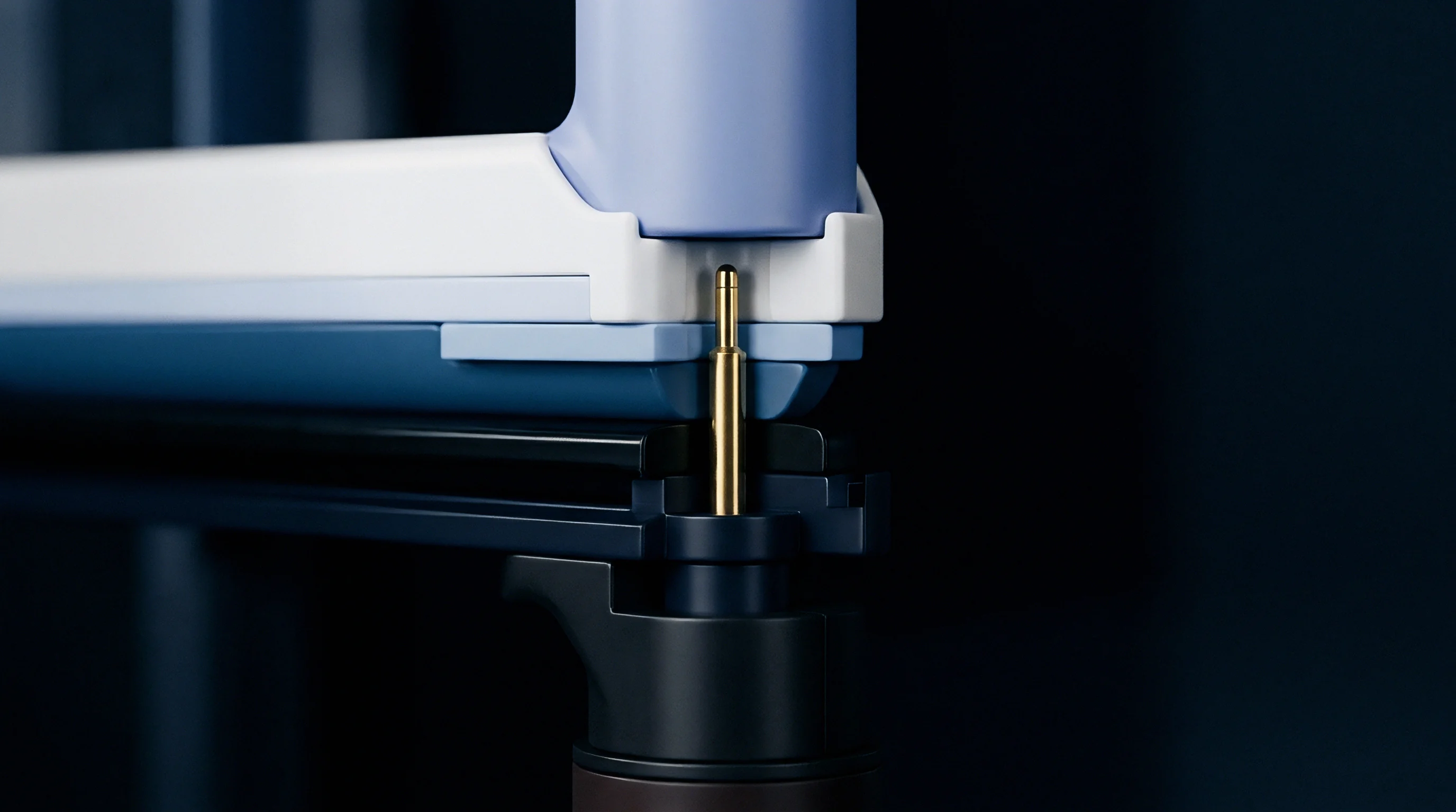
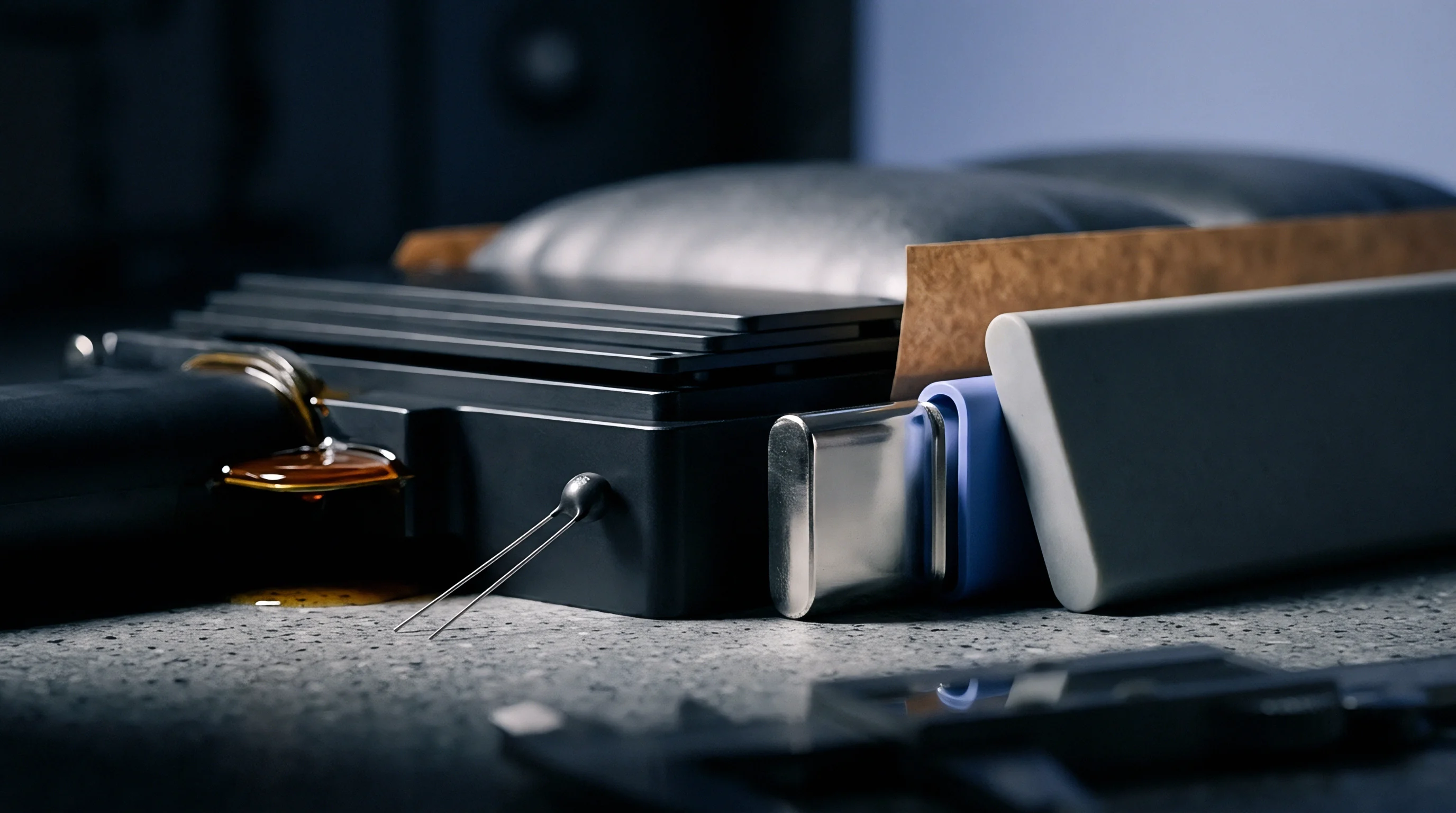
Accumulated variations across cells, thermal pads, spring plates, and endplates define the actual operating window of a module. Tolerances must balance manufacturing capability against the strict pressure limits solid-state chemistries require.

Dimensional Stackup Budgeting
Variations in pouch thickness and spring height set the initial pre-load range. In a 12-cell module, manufacturing tolerances accumulate across several components. Calculating both worst-case and root-sum-square variations determines whether spring plate displacement can accommodate assembly tolerances alongside swelling during operation.
| Component Parameter | Nominal Value (mm) | Tolerance Band (mm) | Worst-Case Impact (mm) | RSS Impact (mm) |
|---|---|---|---|---|
| Cell Thickness (12 cells) | 60.00 | +/- 0.12 per cell | +/- 1.44 | +/- 0.42 |
| Thermal Interlayer Pads (13 pads) | 13.00 | +/- 0.05 per pad | +/- 0.65 | +/- 0.18 |
| Spring Plate Height (2 plates) | 6.00 | +/- 0.10 per plate | +/- 0.20 | +/- 0.14 |
| Structural Frame Clearance | 80.00 | +/- 0.25 frame total | +/- 0.25 | +/- 0.25 |
| Total Assembly Stack Envelope | 159.00 | Calculated Variation | +/- 2.54 | +/- 0.53 |
Beginning of Life to End of Life Envelope Mapping
Uncharged lithium stacks mark the minimum mechanical boundary, while fully plated end-of-life cells define peak stroke. For a 12-cell stack with a 1.8 mm stroke between 0 percent state-of-charge at beginning of life and 100 percent state-of-charge at end of life, adding the 0.53 mm root-sum-square assembly tolerance requires a spring plate working range of at least 2.86 mm to avoid bottoming out or losing required contact pressure.
Exceeding the maximum structural load specified in ISO 12405-4 invalidates cell supplier swelling warranties across the entire module assembly.
Incorporating ISO 12405-4 Annex C clauses into the procurement specification forces cell manufacturers to warrant volumetric swelling curves under specific mechanical boundary conditions rather than free-expansion states.
Fixture
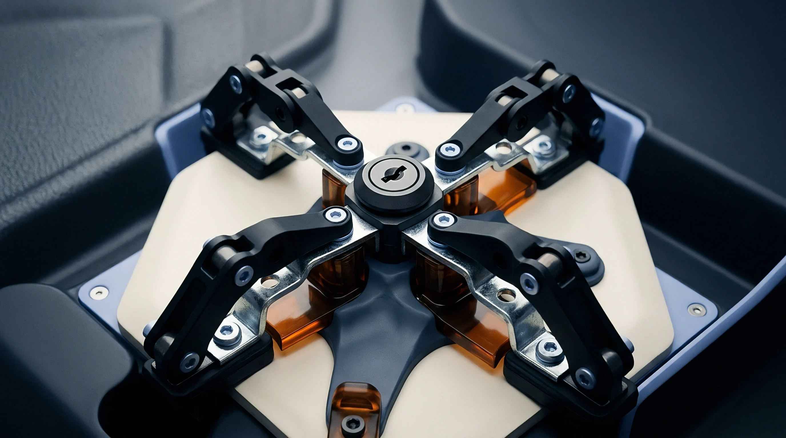
Assembly procedures for solid-state modules use pre-compression tooling to lock structural frames at set torque or load targets. Automated lines use controlled-displacement presses with multi-axis force transducers to record initial load curves.
Pre-Load Compression Calibration
Pressing frames directly during closure secures uniform contact pressure before side straps or bolts are tightened. Automated compression fixtures apply target load profiles while measuring stack deflection in real time, allowing technicians or systems to select custom shim plates or adjust bolt depths.
In-line pre-load calibration fixtures eliminate dimensional variance accumulated during manual stack compression.
In-Line Force Displacement Verification Procedures
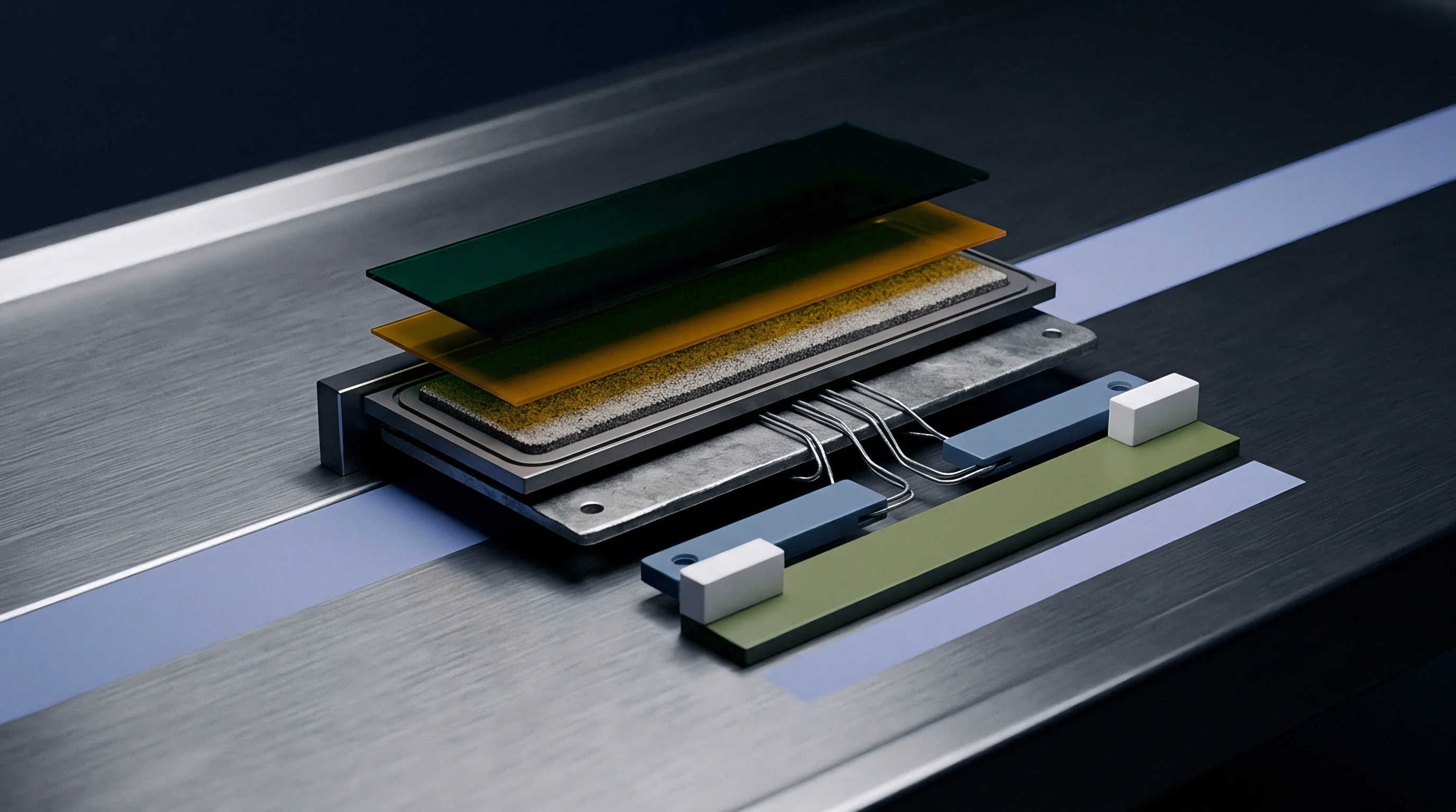
Automated production stations record stroke distance and reaction force during frame closure. The following verification sequence secures baseline module compression:
- Position the uncompressed 12-cell stack in the assembly nest, interleaving thermal pads and spring plates.
- Lower the servo-driven platen at 0.5 millimeters per second until reaching a touch-force threshold of 50 Newtons.
- Advance the platen under force control to the 2.0 MPa target pre-load, recording total stroke travel.
- Verify that total stroke falls within the statistical process control band of 4.2 mm to 4.8 mm.
- Insert structural locking pins or torque housing tie-rod bolts to 12 Newton-meters while holding platen force constant.
- Release the press and record the spring plate elastic bounce-back force using embedded load sensors.
Miscalibrating tooling displacement sensors during assembly crushes localized regions of the cells, causing micro-short circuits, accelerated self-discharge, and premature module teardown.

Seam
Contracts for solid-state battery modules divide performance responsibilities between cell expansion limits and module restraint. Integrators and cell vendors establish clear warranty boundaries covering mechanical degradation, creep, and volume growth.
Interface Responsibility Boundaries
Cell manufacturers specify maximum operating compression and peak swelling across cycle life, while integrators supply spring systems that keep contact forces within those bounds under thermal swing and dynamic shock.
| Interface Domain | Primary Parameter | Cell Supplier Ownership | Pack Integrator Ownership |
|---|---|---|---|
| Volumetric Expansion | Anode Thickness Growth | Warrant cell thickness vs cycle count curve | Provide expansion space within enclosure |
| Contact Pressure | Interfacial Clamp Force | Define min/max MPa operational window | Design spring plate spring rate and stack stroke |
| Mechanical Creep | Pre-load Loss Over Time | Validate electrolyte compressive yield point | Specify low-creep spring steel alloys |
| Assembly Pre-Load | Initial Closing Force | Supply cell thickness grading data | Execute calibrated force-displacement assembly |
Warranty Seam Allocation
If stack pressure drops because spring plates creep beyond specified limits, responsibility for resulting failures rests with the pack integrator. Conversely, if cell thickness expansion exceeds agreed datasheet curves, the cell vendor covers structural deformation or premature capacity loss.
- Cell Free-Expansion Curves Certified expansion measurements under zero-restraint laboratory conditions establish baseline material swelling.
- Spring Stiffness Certificates Mill test reports and lot-level load-deflection certificates confirm spring plate compliance with force specifications.
- In-Line Pre-Load Records Traceable assembly force-displacement logs verify that modules left the factory within pre-load tolerances.
Documenting spring plate strain, displacement curves, and thermal histories during validation builds an auditable technical file to resolve warranty disputes among cell vendors, pack integrators, and OEM warranty funds.